Objectives
After studying this unit, the student will be able to:
• State the purpose and general principles of electric motor control
• State the difference between manual and remote control
• List the conditions of starting and stopping, speed control, and protection of electric motors
• Explain the difference between compensating and definite time delay action
There are certain conditions that must be considered when selecting, designing, installing, or maintaining electric motor control equipment. The general principles are discussed to help un derstanding and to motivate students by simplify ing the subject of electric motor control.
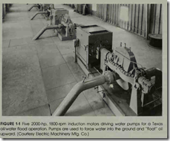
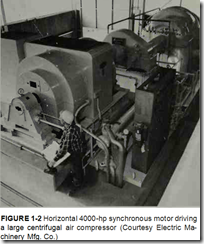
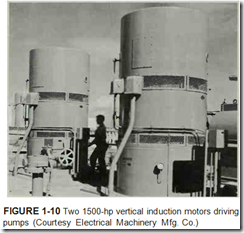
Motor control was a simple problem when motors were used to drive a common line shaft to which several machines were connected. It was simply necessary to start and stop the motor a few times a day. However, with individual drive, the motor is now almost an integral part of the ma chine and it is necessary to design the motor con troller to fit the needs of the machine to which it is connected. Large installations and the problems of starting motors in these situations may be ob served in figures 1-1 and 1-2.
Motor control is a broad term that means any thing from a simple toggle switch to a complex system with components such as relays, timers, and switches. The common function of all con trols, however, is to control the operation of an electric motor. As a result, when motor control equipment is selected and installed, many factors must be considered to insure that the control will function properly for the motor and the machine for which it is selected
MOTOR CONTROL INSTALLATION CONSIDERATIONS
When choosing a specific device for a partic ular application, it is important to remember that the motor, machine, and motor controller are in terrelated and need to be considered as a package. In general, five basic factors influence the selection and installation of a controller.
1. ELECTRICAL SERVICE
Establish whether the service is direct (de) or alternating current (ac). If ac, determine the frequency (hertz) and number of phases in addition to the voltage.
2. MOTOR
The motor should be matched to the electri cal service, and correctly sized for the rnachine load in horsepower rating (hp). Other considerations include motor speed and torque. To select proper protection for the motor, its full load current rating (FLC), service factor (SF), time rating (duty), and other pertinent data-as shown on the motor nameplate-must be used.
3. OPERATING CHARACTERISTICS OF CONTROLLER
The fundamental tasks of a motor controller are to start and stop the motor , and to pro tect the motor, machine, product , and oper ator. The controller may also be called upon to provide supplementary function s su ch as reversing, jogging or inching, plugging , op erating at several speeds or at redu ced level s of current and motor torque . (Sec Glossary .)
4. ENVIRONMENT
Controller enclosures serve to provid e safety
protection for operating personnel by preventing accidental contact with live parts. In certain applications, the controller itself must be protected from a variety of environ mental conditions which might include:
• Water, rain, snow or sleet
• Dirt or noncombustible dust
• Cutting oils, coolants or lubricants
Both personnel and property require protec tion in environments made hazardous by the presence of explosive gases or combustible dusts.
5. ELECTRICAL CODES AND STAN DARDS
Motor control equipment is designed to meet the provisions of the National Electrical Code® (NEC®). (National Electrical Code® and NEC ® are registered trademarks of the National Fire Protection Association Inc., Quincy, MA 02269.) Also, local code re quirements must be considered and met when installing motors and control devices. Presently, code sections applying to motors, motor circuits, and controllers and industrial control devices are found in Article 430 on motors and motor controllers, Article 440 on air conditioning and refrigeration equip ment, and Article 500 on hazardous locations of the NEC.
The 1970 Occupational Safety and Health Act (OSHA) as amended, requires that each employer furnish employment in an environment free from recognized hazards likely to cause serious harm.
Standards established by the National
Electrical Manufacturers Association (NEMA) assist users in the proper selection of control equipment. NEMA standards provide practi cal information concerning the construction, testing, performance, and manufacture of motor control devices such as starters, relays and contactors.
One of the organizations that actually
test for conformity to national codes and standards is Underwriters’ Laboratories (UL). Equipment that is tested and ap proved by UL is listed in an annual publi cation, which is kept current by means of bimonthly supplements to reflect the latest additions and deletions. A UL listing does not mean that a product is approved by the NEC. It must be acceptable to the local au thority having jurisdiction.
PURPOSE OF CONTROLLER
Some of the complicated and precise auto matic applica’tions of electrical control are illus trated in figures 1-3 and 1-6. Factors to be consid ered when selecting and installing motor control components for use with particular machines or systems are described in the following paragraphs.
Starting
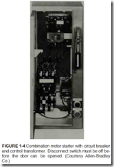
The motor may be started by connecting it directly across the source of voltage. Slow and gradual starting may be required, not only to pro tect the machine, but also to insure that the line current inrush on starting is not too great for the power company ‘s system. Some driven machines may be damaged if they are started with a sudden turning effort. The frequency of starting a motor is another factor affecting the controller. A com bination motor starter with circuit breaker and control transformer is shown in figure 1-4.
Stopping
Most controllers allow motors to coast to a standstill. Some impose braking action when the machine must stop quickly. Quick stopping is a vital function of the controller for emergency stops. Controllers assist the stopping action by re tarding centrifugal motion of machines and low ering operations of crane hoists.
Reversing
Controllers are required to change the direc tion of rotation of machines automatically or at the command of an operator at a control station. The reversing action of a controller is a continual process in many industrial applications.
Running
The maintaining of desired operational speeds and characteristics is a prime purpose and func tion of controllers. They protect motors , operators machines, and materials while running .There are many different types of safety .
and devices to protect people, equipment and in dustrial production and processes against possible injury that may occur while the machines are running.
Speed Control
Some controllers can maintain very precise speeds for industrial processes. Other controllers can change the speeds of motors either in steps or gradually through a continuous range of speeds.
Safety of Operator
Many mechanical safeguards have been re placed or aided by electrical means of protection . Electrical control pilot devices in controllers pro vide a direct means of protecting machin e opera tors from unsafe conditions.
Protection from Damage
Part of the operation of an automatic machine is to protect the machin e itself and the manu fac tured or processed material s it handl es. For ex ample, a certain machine control function may be the prevention of conveyor pileups. A machi ne control can reverse, stop , slow , or do wh atever is necessary to protect the machine or processed materials.
Maintenance of Starting Requirements
Once properly installed and adjusted, motor starters will provide reliable operation of starting time, voltages, current, and torques for the benefit of the driven machine and the power system. The National Electrical Code, supplemented by local codes, governs the selection of the proper sizes of conductors, starting fuses, circuit breakers, and disconnect switches for specific system require ments.
MANUAL CONTROL
A manual control is one whose operation is accomplished by mechanical means. The effort re quired to actuate the mechanism is almost always provided by a human operator. The motor may be controlled manually using any one of the following devices.
Toggle Switch
A toggle switch is a manually operated elec tric switch. Many small motors are started with toggle switches. This means the motor may be started directly without the use of magnetic switches or auxiliary equipment. Motors started with toggle switches are protected by the branch circuit fuse or circuit breaker. These motors gen erally drive fans, blowers, or other light loads.
Safety Switch
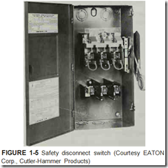
In some cases it is permissible to start a motor directly across the full line voltage if an externally operated safety switch is used, figure 1-5. The mo tor receives _starting and running protection from dual-element, time-delay fuses. The use of a safety switch requires manual operation. A safety switch, therefore, has the same limitations common to most manual starters.
Drum Controller
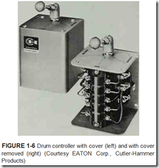
Drum controllers are rotary, manual switch ing devices which are often used to reverse motors and to control the speed of ac and de motors. They are used particularly where frequent start, stop, or reverse operation is required. These con trollers may be used without other control com ponents in small motors, generally those with frac tional horsepower ratings. Drum controllers are used with magnetic starters in large motors. A drum controller is shown in figure 1-6.
REMOTE AND AUTOMATIC CONTROL
The motor may be controlled by remote con trol using push buttons, figure 1-7. When push button remote control is used or when automatic devices do not have the electrical capacity to carry the motor starting and running currents, magnetic switches must be included. Magnetic switch con trol is one whose operation is accomplished by electromagnetic means. The effort required to ac tuate the electromagnet is supplied by electrical energy rather than by the human operator. If the motor is to be automatically controlled, the follow ing two-wire pilot devices may be used.
Float Switch
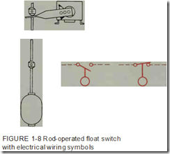
The raising or lowering of a float that is me chanically attached to electrical contacts may start motor-driven pumps to empty or fill tanks. Float switches are also used to open or close piping so lenoid valves to control fluids, figure 1-8.
Pressure Switch
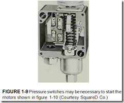
Pressure switches are used to control the pressure of liquids and gases (including air) within a desired range, figure 1-9. Air compressors, for example, are started directly or indirectly on a call for more air by a pressure switch. Electrical wiring symbols are shown as normally closed and nor mally open in figure 1-8.
Time Clock
Time clocks can be used when a definite “on and off” period is required and adjustments are not necessary for long periods of time. A typical requirement is a motor that must start every morning at the same time and shut off every night at the same time, or that switches the floodlights on and off.
Thermostat
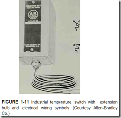
In addition to pilot devices sensitive to liquid levels, gas pressures, and time of day, thermostats sensitive to temperature changes are widely used, figure 1-11. Thermostats indirectly control large motors in air conditioning systems and in many industrial applications to maintain the desired temperature range of air, gases, liquids, or solids. There are many types of thermostats and temper ature-actuated switches.
Limit Switch
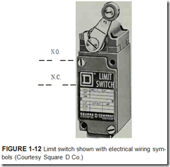
Limit switches, figure 1-12, are designed to pass an electrical signal only when a predeter mined limit is reached. The limit may be a specific position for a machine part or a piece of work, or a certain rotating speed. These devices take the place of a human operator and are often used un der conditions where it would be impossible or impractical for the operator to be present or to ef ficiently direct the machine.
Limit switches are used most frequently as overtravel stops for machines, equipment, and products in process. These devices are used in the control circuits of magnetic starters to govern the starting, stopping, or reversal of electric motors.
