THE MAGNETIC FIELD
A magnetic field is defined as the space around a magnet or a current-carrying conductor. The magnetic field B is represented by lines of induction. Figure 1.4 illustrates the lines of induction of a magnetic field B near a long current-carrying conductor.
The vector of the magnetic field is related to its lines of induction in this way:
1. The direction of B at any point is given by the tangent to the line of induction.
2. The number of lines of induction per unit cross-sectional area (perpendicular to the lines) is proportional to the magnitude of B. Magnetic field B is large if the lines are close together, and it is small if they are far apart.
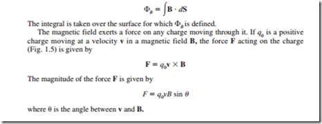
The flux cJB of magnetic field B is given by
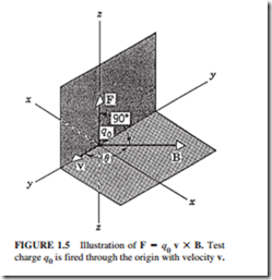
The force F will always be at a right angle to the plane formed by v and B. Thus, it will always be a sideways force. The force will disappear in these cases:
1. If the charge stops moving
2. If v is parallel or antiparallel to the direction of B
The force F has a maximum value if v is at a right angle to B (8 = 90°).
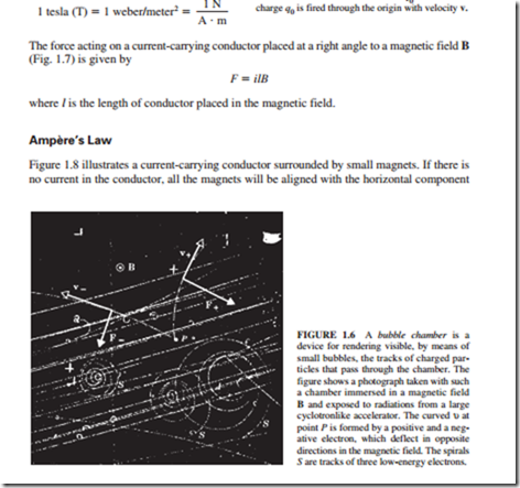
Figure 1.6 illustrates the force created on a positive and a negative electron mov- ing in a magnetic field B pointing out of the plane of the figure (symbol 0). The unit of B is the tesla (T) or weber per square meter (Wb/m2). Thus
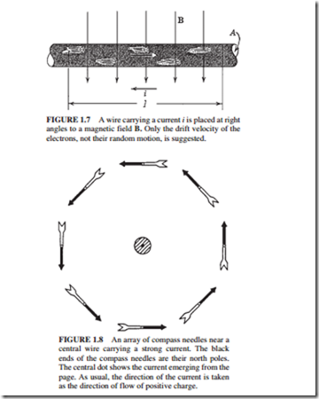
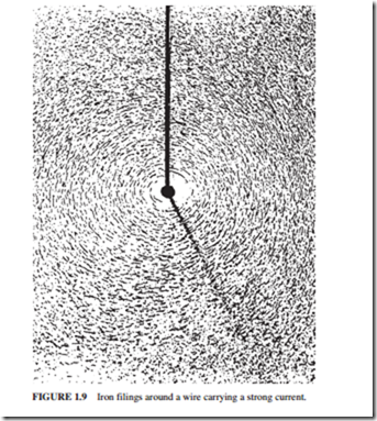
of the earth’s magnetic field. When a current flows through the conductor, the orientation of the magnets suggests that the lines of induction of the magnetic field form closed circles around the conductor. This observation is reinforced by the experiment shown in Fig. 1.9. It shows a current-carrying conductor passing through the center of a horizontal glass plate with iron filings on it.
Ampère’s law states that
where B is the magnetic field, l is the length of the circumference around the wire, i is the current, j.L0 is the permeability constant (j.L0 = 4TIX 10 ried around the circumference.
T ·m/A). The integration is car-
If the current in the conductor shown in Fig. 1.8 is reverse direction, all the compass needles change their direction as well. Thus, the direction of B near a current-carrying conductor is given by the right-hand-rule:
If the current is grasped by the right hand and the thumb points in the direction of the current, the fingers will curl around the wire in the direction B.
Magnetic Field in a Solenoid
A solenoid (an inductor) is a long, current-carrying conductor wound in a close-packed helix. Figure 1.10 shows a “solenoid” having widely spaced turns. The fields cancel between the wires. Inside the solenoid, B is parallel to the solenoid axis. Figure 1.11 shows the lines of B for a real solenoid. By applying Ampere’s law to this solenoid, we have
