ALTERNATING CURRENT
An alternating current (ac) in a circuit establishes a voltage (emf ) that varies with time as
where �m is the maximum emf and w= 2TIv, where v is the frequency measured in hertz (Hz). This type of emf is established by an ac generator in a power plant. In North America, v = 60 Hz. In western Europe and Australia it is 50 Hz. The symbol for a source of alternating emf is . This device is called an alternating-current generator or an ac gen- erator. Alternating currents are essential for modern society. Power distribution systems, radio, television, satellite communication systems, computer systems, etc. would not exist
without alternating voltages and currents.
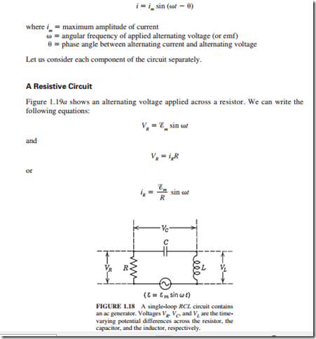
The alternating current in the circuit shown in Fig. 1.18 is given by
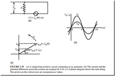
A comparison between the previous equations shows that the time-varying (instantaneous) quantities VR and iR are in phase. This means that they reach their maximum and minimum values at the same time. They also have the same angular frequency w. These facts are shown in Fig. 1.19b and c.
Figure 1.19c illustrates a phasor diagram. It is another method used to describe the situation. The phasors in this diagram are represented by open arrows. They rotate counter- clockwise with an angular frequency w about the origin. The phasors have the following properties:
1. The length of the phasor is proportional to the maximum value of the alternating quantity described, that is, �m for VR and �m/R for iR.
2. The projection of the phasors on the vertical axis gives the instantaneous values of the alternating parameter (current or voltage) described. Thus, the arrows on the vertical axis represent the instantaneous values of VR and iR. Since VR and iR are in phase, their phasors lie along the same line (Fig. 1.19c).
A Capacitive Circuit
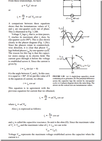
Figure 1.20a illustrates an alternating voltage acting on a capacitor. We can write the fol- lowing equations:
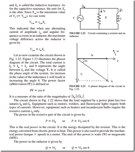
This is the reactive or inductive power in the circuit. It is the power stored in the inductor in the form of a magnetic field. This power is not consumed as the real power is. It returns to the system (power plant and transmission lines) every half-cycle. It is used to create the magnetic field in the windings of the motor. The main effects of reactive power on the system are as follows:
The transmission line losses between the power plant and the load are proportional to iT RT , where iT = iR iL and RT is the resistance in the transmission lines. Therefore, iL is a contributor to transmission losses.
2. The transmission lines have a specific current rating. If the inductive current iL is high, the magnitude of iR will be limited to a lower value. This creates a problem for the utility because its revenue is mainly based on iR.
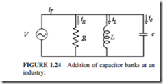
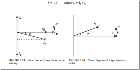
3. If an industry has large motors, it will require a high inductive current to mag- netize these motors. This creates a local- ized reduction in voltage (a voltage dip) at the industry. The utility will not be able to correct for this voltage dip from the power plant. Capacitor banks are nor- mally installed at the industry to “correct” the power factor. Figures 1.24 and 1.25 illustrate the correction in power factor.
Angle 8¢ is smaller than 8. Therefore, the new power factor (cos 8¢) is larger than the previous power factor (cos 8). Most utilities charge a penalty when the power factor drops below 0.9 to 0.92. This penalty is charged to the industry even if the power factor drops once during the month below the limit specified by the utility. Most industries use the following methods to ensure that their power factor remains above the limit specified by the utility:
a. The capacitor banks are sized to give the industry a margin above the limit specified by the utility.
b. The induction motors at the industry are started in sequence. This is done to stagger the inrush current required by each motor.
Note: The inrush current is the starting current of the induction motor. It is normally 6 to 8 times larger than the normal running current. The inrush current is mainly an inductive current. This is due to the fact that the mechanical energy (torque X speed) developed by the motor and the heat losses during the starting period of the motor are minimal (the real power provides the mechanical energy and heat losses in the motor).
c. Use synchronous motors in conjunction with induction motors. A synchronous motor is supplied by ac power to its stator. It is also supplied by direct-current (dc) power to its rotor. The dc power allows the synchronous motor to deliver reactive (inductive) power. Therefore, a synchronous motor can operate at a leading power factor, as shown in Fig. 1.26. This allows the synchronous motors to correct the power factor at the industry by compensating for the lagging power factor generated by induction motors.
The third form of power used is the apparent power. It is given by
The unit of this power is voltamperes (VA) or megavoltamperes (MVA). This power includes the combined effect of the real power and the reactive power. All electrical equipment such as transformers, motors, and generators are rated by their apparent power. This is so because the apparent power specifies the total power (real and reac- tive) requirement of equipment.
