Fuel System Service
AIR CLEANER
An excessive amount of dust, dirt and oil on the cleaner body and at the points of air entry are definite indications of a dirty air cleaner. When such conditions are found, remove the air cleaner and clean it thoroughly.
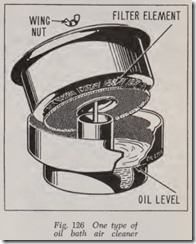
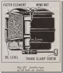
Several types and many shapes of air cleaners are used, two of the more common types being shown in Figs. 126 and 127. Each type requires a certain amount of disassembly to inspect the oil level and to determine the condition of the oil within the reservoir. Some types do not have the oil bath feature, in which case the filtering ele ment is merely oil-wetted.
The paper element type filter, introduced on many cars in 1957, should be cleaned and in spected every 5000 miles under normal operating conditions (every 1000 miles under dusty operat ing conditions). Every 12,000 miles the element should be replaced with a new one. To clean the element, repeatedly drop it squarely on a flat surface from a height of two inches until all loose dust has been removed. Turn the element over and repeat the process. Do not clean by any other method or the element will be damaged. Do not wash, air blast or oil element.
On the oil-wetted and oil-bath type cleaners, Figs. 126 and 127, scrape the dirt from the air cleaner reservoir. Wash the filter element and, after drying it, re-oil with engine oil Set it aside to allow the surplus oil to drain from the element. Then on oil bath type cleaners, wash the cleaner reservoir and wipe it dry. Add oil of special grade to indicated level.
CARBURETOR
Examine the carburetor for fuel leaks at a point where the cover fastens to the float bowl and at the points where threaded caps or lead plugs cover the fuel passages. Inspect all caps covering check valves and jets. Tighten any of these joints that leak.
Clean the fuel strainer at the carburetor.
Tighten the flange nuts or cap screws holding the carburetor gasket by noting the condition of the gasket edge showing at the edge of the flange.
Test the action of the accelerator. It should operate the throttle from. closed to wide open position.
When the fuel used contains a dye for coloring, a fuel leak is sometimes indicated by an accumu lation of the dye on the carburetor, fuel lines or fuel tank. It should be remembered, however, that certain castings such as the fuel pump or car buretor may permit a very slight amount of gas oline seepage which will be indicated by a layer of the dye. This seepage is inconsequential and should be ignored.
Fuel Strainer at Carburetor
Remove the fuel strainer from the carburetor, or remove the cover from the strainer. Wash the strainer in cleaning fluid or clean it with com pressed air. Examine the strainer gasket. Replace it if it is compressed or damaged.
Throttle Control
Examine the throttle control to be certain that the throttle will range from idle to full open posi tion. Examine the carburetor control levers and the rod leading from the accelerator to the con trols. These must be free at all connections and should not bind or rub against the engine or floorboards.
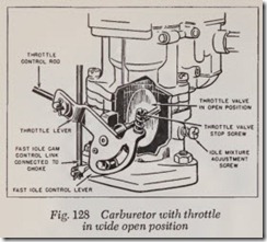
The range of throttle opening can be deter mined by operating the accelerator pedal. The opening range should extend from the point where the idle screw contacts the stop to where the throttle lever stop contacts the full open posi tion lug on th e carburetor body.
The range of throttle opening is determined in the following manner: Remove the air cleaner. Set the choke valve to wide open position. Should the choke be automatic, the valve must be held open unless the engine has been thoroughly warmed.
Open and close the throttle. Observe the action of the throttle valve at the carburetor. The valve should be in a vertical position, Fig. 128, when the accelerator pedal is fully depressed. If not, adjust the length of the accelerator control rod at the threaded ends to obtain the full operating range.
Manual Choke Control
Examine the action of the choke valve to be certain that it operates at full range from open to closed position. When the choke valve disc has a spring-loaded poppet valve as a part of the disc, be sure that the valve is free on the supporting stem and that the spring holding the valve in place is not damaged.
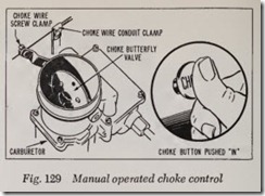
To adjust this type of choke control, Fig. 129, tighten the nut holding the choke control to the instrument panel. Push the choke button in. Tighten the stationary conduit clamp at the car buretor. Loosen the set screw on the choke wire screw clamp. Hold the choke valve fully open and tighten the screw clamp against the wire. Test for extremes of travel as the choke button is moved from open to closed position.
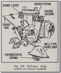
Manifold Mounted Automatic Choke The operation of this type of choke control, Fig. 130, is based upon the combination of intake manifold vacuum, a vacuum operated piston, an offset choke valve and a thermostatic coil spring located in a cavity in the exhaust manifold and connected to the choke lever by a rod.
Heat from the manifold governs the tension of the thermostat coil spring. The fast idle cam oper ates in conjunction with the automatic choke mechanism to provide the correct throttle opening to prevent engine from stalling during warm-up.
To function properly, it is important that all parts be clean and work freely. Other than an occasional cleaning the choke requires no servic ing. It is very important, however, that the choke control unit work freely in the well and at the choke shaft.
Move the choke rod up and down to check for free movement at the pivot. If the unit binds a new choke unit should be installed as the unit is serviced as an assembly only. Do not attempt to repair or change the index setting.
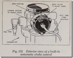
Built-in Automatic Choke Control This type automatic choke control, Fig. 131, is attached to the upper part of the carburetor. The cover is marked with a scale and pointer, and has a mark at the center for a neutral (or “Index”) setting. An arrow on the face of the cover indi cates the direction in which the cover should be turned from the center position to obtain a leaner or richer mixture.
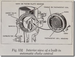
To adjust a choke of this type, Fig. 132, remove the housing attaching screws. Take off the cover with care so that the ton gue on the thermostat coil releases from the choke valve shaft as the cover is moved away from the carburetor body. Remove and clean the screen. Replace the screen. Then install the thermostat coil housing or cover with the marks up. Insert the attaching screws and retainers.
There is a specified setting for all carburetors h aving this type choke control. Lacking this spe cific information, turn the housing counter-clock wise until the pointer and the coil housing marks show neutral ( “0” or “Index”), then adjust two notches rich. When in this position the choke should close and seat against the carburetor air horn (engine cold) and then move to full open position as the engine warms up to operating temperature. Should it fail to do so, loosen the housing attaching screws and rotate the housing one notch at a time according to the arrow and symbol on the housing, to obtain a leaner or richer setting.
Carburetor Idle Speed and Mixture Adjustment
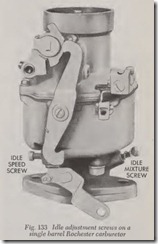
The initial setting of the idle adjustment screw ranges from f to about 2 turns from the seated position of the screw tip.
Turn the adjustment screw clockwise by hand until it seats lightly, Fig. 133. Then open it about one turn. Start the engin e and run it until it reaches normal operating temperature (choke valve wide open).
Slowly turn the adjust!llent screw to the right a little at a tim e until the engin e shows a tendency to hesitate and stop. Then turn it to the left until the engine runs smoothly. Continue turning the screw to the left until the fuel mixture is rich and the engine lopes or gallops. Again turn the screw to the right until the engine runs evenly.
On two-barr el carburetors there is an idle adjustment screw for each barr el. On four-barrel carburetors there are also two idle adjustment screws on the primar y side of the carburetor. When idle ports are provid ed on the secondary side they are non -adjustabl e or they arc rendered non-fun ctional by being blo cked with gaskets.
Wh en adjusting the idle mixture on two- and four-ba rr el carburetors, adjust one screw at a time until the engine runs smoothly as directed above. Then adjust the other screw in like mann er.
Af ter the idle mixture has been adjusted, reduce the engine speed by backin g out the throttle ad justing screw until the en gine idle speed is satis factory. Each car manufacturer specifies a definite idle speed, usually betw een 350 and 500 engine rpm. This data is important on cars with auto matic transmission because if the speed is too great the car will creep forward when standin g with engine running and shift lever or button in Drive position.
Carburetor Removal
The general procedur e for removing a carbu retor is to remov e the air cleaner. Disconnec t choke and throttle controls, fuel pipe and vacuum advance pipe. Unfasten carburetor from manifold
flange and lift it off the engine.
Handle the carburetor carefully and hold it in an upright position. Do not allow it to tilt, for if there is an accumulation of sediment in the fuel bowl it will become agitated, pass into the jet openings and clog them. Never place the car buretor in a location where dirt can enter any opening. It is a good idea to mask or tape the carburetor air horn and fuel inlet openings.
Carburetor Installation
When the carburetor used is a replacement, becertain that it is similar in all respects to the one removed. The attaching flange must be the same, the fuel connections must match; the throttle lever, the choke control and all connections must be identical.
Be certain that the gaskets are in good condition. If the carburetor has a governor, any port holes cut through the gasket must align with the governor flange and also match the holes in the carburetor. Tighten the carburetor flange nuts evenly and securely. Connect the throttle and choke control, the fuel pipe and vacuum advance pipe. Assemble the air cleaner to the carburetor and adjust the carburetor idle mixture and speed as outlined above.
Before attempting to start the engine, pump the carburetor full of fuel by cranking the engine with the starter with the ignition off.
FUEL PIPES
Examine all fuel pipes carefully for cracks, dents or wear. The pipe must be securely fastened and all loose clips and clamps securely tightened. If the pipe rubs against the car frame or strikes any sharp metal edges, move it slightly to clear the object.
Never bend or change the shape of a sweater steel fuel pipe as this will cause the seam to open, starting a leak. Inspect and carefully tighten the fuel pipe connections at units such as the tank, fuel filter, fuel pump and carburetor.
When a flexible connection is used to connect a fuel unit to the fuel pipe, examine it for leaks and cracks and replace it if damaged. The new flexible hose must be long enough to sag when connected. This allows it to flex with movement between the units, instead of breaking, when the car is oper ated on rough roads.
Fuel Pipe Connections
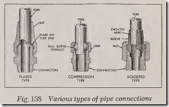
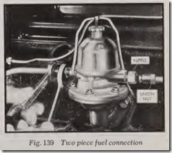
Fig. 138 pictures various types of fuel pipe con nections. When the connections are of two pieces (a nipple that screws into the unit and a nut that is screwed into the nipple) use two wrenches for loosening or removing the nut, Fig. 139. When installing a union nut to a fuel connection, start it by hand and turn finger tight; then tighten it further with a wrench. This will prevent cross threading.
When tightening such a fuel pipe connection, use two wrenches, Fig. 139. First loosen the union nut, tighten the nipple, and then retighten the union nut. Tightening in this manner prevents twisting off.
Fuel Pipe Replacement
, It is not always necessary to replace a cracked or broken fuel pipe, nor is it always necessary to remove the pipe to complete a repair. However, if the pipe is broken beyond the immediate range of the coupling point it should be replaced.
First disconnect the unions coupling the pipe to the fuel units. Next, loosen or remove the clamps holding the pipe in place. Remove the pipe.
The new pipe must be the same size, have the same form and the same length as the old. Loosely clamp the pipe in place. The connections should match those of the fuel unit to which it couples. Start the union nuts by hand and screw them finger tight. If there is a strain or tension as the pipe is coupled, it will cause the pipe to break or leak later on. It is permissible, with this coupling operation, to slightly bend a copper pipe to conform to the fuel unit. However, never bend a sweated steel fuel pipe beyond a slight degree, as bending breaks the seam. Tighten the clamps holding the pipe in place and tighten the unit or coupling nuts.
Fuel Pipe Repair
If the pipe is broken at a point next to the con nection, the pipe can be repaired. Slide the union nut along the pipe, away from the end. File the end of the pipe squarely. Clean the filings from the pipe and apply a new sealing member. This seal may be a ferrule, or a nut and ferrule com bined, or a nut that compresses against the pipe when under tension, Fig. 138. When such a repair is made, be sure that a strain on the pipe is not created because of its shorter length.
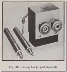
When the pipe has a flared end, it too at times can be repaired without removing the pipe, pro viding there is sufficient space to attach and oper ate the flaring tool, Fig. 140. When such a repair is made, first cut off the damaged flare, clean the filings from the pipe, and place the pipe in the flaring tool so that the end of the pipe contacts the stop pin (left view, Fig. 141). Tighten the nuts holding the pipe in the flaring tool and remove the stop pin. Apply lubricating oil on the end of the pipe. Then flare the end of the pipe with the die as shown in the center and right views, Fig. 141, using a hammer on the tool to form the double lap flare shown.
If the pipe should crack while it is being flared, it does so because it has become hardened with use, vibration, or compression. If the cracked pipe is made of copper, cut off the end and soften the metal by annealing. This is accomplished by hold ing the end of the pipe in the flame of a blow torch. This should be done after removing the pipe from the vehicle and being certain that it has been drained completely. Heat the pipe until it becomes a light red in color. Then plunge it im mediately in cold water and allow it to cool. This procedure softens the pipe so that it can be flared without cracking.
FUEL FILTERS
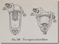
Fig. 136 illustrates two types of fuel filters. Re move the drain plug or bowl to empty the filter. Should a noticeable amount of water or dirt be present, the filter should be cleaned.
As filter elements are fragile, wash them carefully in a cleaning fluid. Gently brush it or clean it with compressed air of low pressure. Insert it carefully into the filter body. Examine gaskets on the filter bowl and (if so equipped) on the filter element as well.
If the filter employs a knurled nut to secure the element, assemble the element with care and fasten it finger tight. Never use pliers or a wrench to tighten the element. Install the cover and tighten the screw holding it in place.
When installing the filter to the carburetor, or at any other point in the fuel system, be sure the outlet, stamped “outlet” or “out”, is upstream, in terms of fuel flow, from the inlet.
Start the engine and allow it to run until the fuel pipe and filter are filled with fuel. Inspect the gasket and drain plugs for leaks.
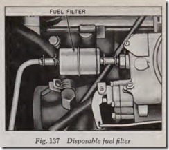
Disposable fuel filters, one of which is shown in Fig. 137, are now widely used. A sealed unit designed for a specific service life (usually 12,000 miles), they cannot be disassembled for cleaning and must be replaced periodically when no longer effective in removing foreign matter from the fuel. They are generally equipped with a male con nector at either end for use with flexible gasoline resistant rubber or plastic fuel tubing. When in stalling this type filter care should be taken that it be inserted in the line pointing in the right direc tion. An arrow or an appropriate legend is usually stamped on the case to indicate the proper direc tion of fuel flow.
ELECTRIC FUEL PUMP
Electric fuel pumps cannot be serviced on the car except to test pump output and/or pressure and if these are nil, to check to be certain that the malfunction is not caused by a current supply failure. When the engine is idling, fuel pressure at the carburetor should be 43f pounds. Fuel flow under the same conditions should be 1 pint or more in 30 seconds.
If fuel flow or pressure is inadequate or non existent, the voltage supply should be checked at the pump electrical connections on top of the fuel tank. If 12 volts or more are available at that point, the pump is defective and should be re placed. If, no current is flowing to the pump further electrical tests should be made.
These electrical pumps utilize a multiple current supply system. Electricity for the pump is ob tained from the starter circuit on engine start-up and from the ignition switch under control of the engine oil pressure when the engine is running. Oil pressure must be 3 pounds or more when the engine is running to energize the fuel pump. Trouble in any of these electrical circuits will cause fuel pumping troubles.
Electric fuel pumps of the turbine type are easily removed and installed. The electrical con nectors must be removed before the pump is removed from the fuel tank; these connections are reached from under the car. Access to the pump is gained by pulling back the trunk floor mat and then removing the screws that hold the gas gauge tank unit and pump cover plate to the tank. After disconnecting the fuel hose from the cover plate, remove the entire unit from the tank by unscrew ing the retaining cam ring. The pump is taken off the tank unit by first releasing it from the fuel pipe coupling and then removing the two elec trical connections before pulling it free. Reverse the procedure to install the pump.
MECHANICAL FUEL PUMP
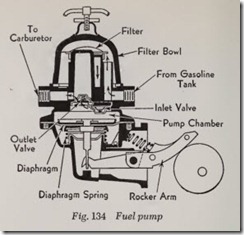
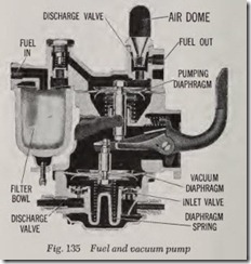
In most passenger car engines a cam on the camshaft engages with, and directly actuates, the face of the rocker arm of the fuel pump, Figs. 134 and 135.
Examine the inside of the sediment bowl for dirt or water. A glass bowl can be inspected with out removal. A met al bowl or metal cover, how ever, must be removed for inspection. If n eces sary, rem ove th e sedim ent bowl and thoroughly clean it. Wash the screen in cleaning fluid or clean with compressed air. Us e a new gasket when in stalling the bowl, as the pu mp will not operate with an air leak at this point . This operation must be perf ormed often er during freezing weath er as ice in the bowl will stop the fuel flow.
Inspect the fuel connection s for leaks, as indi cated by fuel dripping or seeping from joints , and tighten if necessary. Tighten the cover screws these hold the pump together and also hold the diaphragm in place.
Fuel Pump Testing
Although special testing gauges are available for testing fuel pumps, as will be explain ed und er Fuel Pump Service, an emergency meth od is as follows:
First be sure there is fuel in the supply tank. Disconnect the fuel pipe at the carburetor. Test the fuel pump by cranking the engine with the starter (ignition off). If no fuel is forced from th e open end of the fuel pipe, the pump is defective and should be repaired or replaced. Be certain, however, that the pump has been properly in spected and tightened as previously outlined .
Fuel Pump Removal
Disconnect the fuel pipes at the pump. Clean the dirt and grease from the base of the pu mp at the point where it is fastened to the engine. Un fasten the pump from the engine and lift it out, together with the gasket.
Fuel Pump Installation
If the pump is a replacement compare it with the one removed . Be certain that it is the same type and size. Identify it further by the numbers and letters stamped on it, particularly the number
on the pump arm. Examine the replacement pump to be sure the connections are clean. Remove any dust caps or plugs from the connections. Transfer the connections from the old pump before the new pump is installed and securely tighten them. Place a new gasket on the studs of the fuel pump mounting or over the fuel pump opening in the crankcase, holding it in position with gasket seal or grease.
Insert the pump rocker arm through the open ing in the crankcase. Slide the pump into position and tighten the nuts or cap screws. Start the union nuts by hand and then tighten them to the connections with a wrench. Prime the pump by crank ing the engine with the ignition off. Then turn on the ignition to start the engine and examine all connections for fuel leaks.
FLEXIBLE FUEL LINES
Tubing under this category is meant to include only plain, unreinforced rubber and plastic fuel lines. Other flexible piping, such as the reinforced length connecting the fuel pump with the gas line, have standard connectors of the type described in the preceding section.
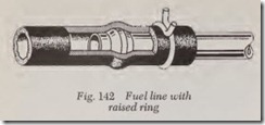
Widely used for fuel, vacuum, windshield washer and other low pressure purposes, this type line comes in a complete range of inside and outside diameters and is very easy to install. When used in fuel service, the rubber or plastic tubing is secured over rigid connectors as shown in Fig. 142. Notice that these male connectors have a raised ring, like the ball sleeve or ferrule shown with the compression fitting in Fig. 138, over which the tube must pass. A ring clamp or threaded clamp is placed on the far side of the raised ring to secure a leak-proof seal. In vacuum and other less critical applications, a plain tube rigid connector, without the raised ring, can be us ed. This type connection, shown in Fig. 143, is not r ecommended for fuel system use. Another precaution is that only certain compositions of rubber and plastic can be exposed to gasoline without disintegratin g, thus, the tubing must be of one of these compositions. Further, even some of thes e have a tendency to “age” and become brittle over a period of time and should be inspected periodically .
FUEL TANK
Examine the anchor bands or straps securing the tank to the chassis. These should be free of cracks or bends. Tighten the straps. If they are lined with web strips, rubber or some such ma terial, be sure that the strips are in place between the bands and tank before tightening.
Inspect the tank for wear and for leaks, par ticularly at the points where the tank seats in the bracket or carrier. Inspect the filler neck at the point where it is soldered and riveted to the tank, or be sure it is not loose or leaking.
Check to see that the tank vent is open. If the vent is located in the filler cap, poke through the opening with a piece of wire. If the vent consists of a tube anchored inside the filler neck, it must extend to the top, and must be so placed that both fuel and air will How freely. The vent may also be located in the fuel gauge housing. Regardless of its location, the vent hole must be open; if not the fuel will not How, and the tank may even collapse due to the vacuum created inside the tank.
Method of Tightening Fuel Tank
If the tank is found to be loose, tighten as follows: First, oil the threaded ends of the bands and attaching nuts with light engine oil or with a special penetrating oil. As the oil penetrates the threads, it will allow the nuts to turn easily and will prevent the bands or straps from twisting when the wrench is applied.
Tighten the screws holding the fuel gauge to the tank, and should there be a fuel leak at this point which tightening will not stop, replace the gasket. While you are in the area, examine the fuel gauge wire for damage and the terminals for tightness. This should be done at the instrument panel as well.
When Water Is in System
When water accumulates in the fuel tank, it must be drained and all fuel units must be in spected to determine whether or not water has lodged in them. Remove the drain plug and drain the tank, raising first one end of the tank and then the other, to be sure all the water runs out.
If alcohol in any form is available, pour one quart in the fuel tank. The alcohol will gather and mix with the scattered drops of water at the bottom of the tank. When the mixture of alcohol and water has been well agitated, remove the plug and allow the mixture to drain.
When water has accumulated to any degree inthe tank, undoubtedly it is also present in other fuel units, and it may be necessary to drain them also.
Fuel Tank Removal
To remove a fuel tank, first drain the fuel into clean containers of a type to comply with all safety requirements. Then disconnect the fuel pipe. If the fuel filler neck is soldered and riveted to the tank, it cannot be removed. Other types can be removed when necessary. If the filler neck is coupled to the tank with a short section of hose, it can be removed by loosening the attaching clamps. If it is attached by a spanner nut, it can be taken off easily by use of a spanner wrench.
Disconnect the fuel gauge. The connections to the gauge are readily accessible, either directly or through a hand hole provided for the purpose. Oil the threads on the bands or straps and remove the nuts. It may be necessary to remove a shield or guard before lifting the tank out of the vehicle.
Fuel Tank Installation
Before installing a replacement tank, inspect it carefully to make sure that it is a duplicate of the one removed. Using the light of a flash lamp or a well protected electric lamp on an extension cord, see that the inside of the tank is perfectly clean.
If the new tank is not equipped with a fuel gauge, transfer the old gauge, installing it with a new gasket and tightening securely. Cement the webbing or rubber strips on the mounting brack ets and set the tank in position. Oil the threads on the tank hold-down straps and be sure the nuts are free on the threads. Set the bands or straps on the tank with the threaded ends projecting through the mounting brackets. Tighten the nuts. Couple the fuel pipe. Attach the filler neck if it is the detachable type. Connect the fuel gauge.
Fill the tank and, at the same time, observe the action of the gauge. It should register a rise from “empty” to “full” as the tank is filled. Since the gauge float does not rest on the bottom of the tank, some fuel will be added before the gauge starts to read above “empty”.
INTAKE MANIFOLD
Test for Air Leaks
With the engine idling, test the intake manifold gasket for air leaks by spreading oil from the spout of an oil can along the gasket edges. An air leak is indicated when oil is drawn past the gaskets by the suction of the engine. Tighten the nuts or cap screws holding the intake manifold to the engine, and retest for leaks. If tightening fails to stop the air leaks, replace the gaskets.
When making a test for leaky manifold gasket, examine the pipe or tube leading to the wind shield wiper for air leaks (if the wiper is electric, there will be no such tube). Test with oil in a manner similar to the gasket test. An air leak in this pipe, or one at a joint, can be detected by a shrill, hissing sound. A short section of rubber tubing is usually employed to provide a flexible connection between the intake pipe and the wind shield wiper tube. Replace any broken or rotted rubber tubing and any broken metal tubing.
WINDSHIELD WIPER TUBING REPLACEMENT
Unless an electric wiper is fitted, the windshield wiper operates from the vacuum created in the intake manifold of the engine. As the speed of the engine increases, or when the engine operates at full throttle, the vacuum in tl1e manifold de creases. Unless a vacuum booster is used in con nection with it, Fig. 135, the wiper will cease to operate with the engine operating at full throt tle. Therefore, when testing the action of the wiper, be sure that the test is made with the engine running at slow speed.
Two pieces of metal tubing, connected by a rubber tube, usually serve as a vacuum line to the manifold. The rubber tube is used because move ment of the engine, independent to that of the car body, would break a continuous metal tube. The rubber tube is easily pulled off the metal tube and replaced. However, the metal tube may be in stalled behind the dash pad and through the windshield post; if so, it can be reached for re placement only by removing some interior trim.
MANIFOLD HEAT CONTROL VALVE
The exhaust manifold conveys the exhaust gases away from the engine. However, before the hot gas is completely dissipated, it is utilized to further the vaporization of the fuel. This is accomplished by diverting a portion of the ,exhaust gas to a “hot spot” in the intake manifold or by conveying it through a passage surrounding the point where fuel enters into the intake manifold.
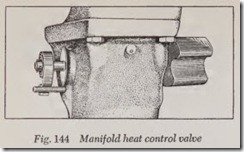
The heat is usually directed to the hot spot by a bimetal thermostatically controlled valve, attached to a shaft having supporting bearings in the manifold, Fig. 144.
The shaft must turn freely in the bearings in order that the thermostatic spring can move the valve to closed position as the manifold tempera ture increases. Heat will scale the shaft and cause it to bind in the bearings. If the valve does not move freely, it may be loosened by applying pen etrating oil to the shaft and bearings. A solution of washing soda and kerosene may be substituted for the oil. If this method fails, remove the unit and clean the shaft with fine sandpaper or emery cloth.
MUFFLER AND TAIL PIPE
The muffier and tail pipe have no connection with the fuel system but tl1ey do have a direct bearin{on power developed by the engine and on engine performance in general. These two units must always be inspected when a power loss de velops. An accumulation of carbon may clog the muffier, or the tail pipe may be crushed or other wise clogged, thus restricting the escape of ex haust gas and affecting engine power.
Momentarily accelerate the engine to high speed. When the exhaust gas builds up a high pressure in the exhaust system, reduce the engine speed to normal idle. A hissing sound indicates that some part of the system is restricted. The system should then be examined carefully and the obstruction removed.
Inspect the tail pipe and remove any obstruc tion present. If the end of the pipe is clogged, use a screwdriver, sharp stick or other pointed instru ment to open the pipe. If the pipe is kinked, insert a bar or an old axle shaft in the pipe. If necessary, strike the pipe lightly with a hammer as the bar is inserted.
