CAMSHAFT THRUST PLATE
It should be realized that the camshaft must be held in a fore and aft position so that camshaft bearings and bearing journals line up and so that the cams are in line with their tappets. There are the following common ways of doing this.
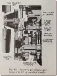
In Fig. 131, a thrust plate or washer is bolted to the front of the cylinder block. The hole in the plate is smaller than the outer diameter of the hub of the sprocket and also smaller than the front camshaft journal. Therefore the plate prevents the camshaft from moving either to front or rear of its correct position.
On all engines equipped with thrust plates it is desirable to install a new thrust plate whenever a new camshaft gear is installed. There should be a slight amount of clearance at the thrust plate, say
.002″.
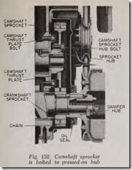
However, on most engines with thrust plates the parts arc so designed that when the camshaft gear is properly installed the correct clearance is obtained. For example, in Fig. 1.31, there is a narrow ring spacer washer between the camshaft and the hole in the thrust plate. The washer insures correct clearance because it is a trifle thicker than the thrust plate and thus prevents drawing up the gear so tight that it might clamp itself to the thrust plate.Fig. 132 illustrates a different construction which accomplishes the same purpose. There is a shoulder on the camshaft sprocket hub which butts against the camshaft and thus provides the required thrust plate clearance.
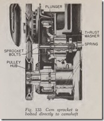
In Fig. 133, there is a thrust washer which prevents the cam sprocket from moving rearward while a spring-backed plunger prevents the cam shaft from moving forward.
In Fig. 134, the thrust plate clearance is correctwhen the nut on the end of the camshaft is drawn up tight, the length of the hub being just right to provide the necessary clearance.
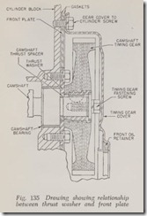
The thrust plate or washer should not be con fused with the engine front plate. Fig. 135 makes this point clear. The thrust washer, which is be tween 3 and 4 inches in diameter, lies within a hole in the front plate. A thrust spacer is located between the camshaft and a hole in the thrust plate. This spacer insures correct lengthwise clear ance between cam gear hub and thrust washer. The latter, it should be noted, is bolted to the front of the block.
Depending on the engine design the fit between the hub of the timing gear or sprocket and its camshaft or crankshaft may be any one of three, namely: ( 1) snug fit, .001″ clearance; ( 2) tight fit,
.0004″ clearance; ( 3) press fit: shaft is .003″ or more larger than hub hole.
With No. 1 it should be possible to remove and replace the gear by hand although gentle tapping with a soft hammer may be required.
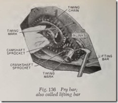
The same may hold b·ue of No.2 although a pry bar, Fig. 136, or a puller may be required to remove the gear. Likewise, installation of the gear may require a hollow drift and a hammer.
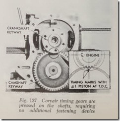
No. 3 demands an arbor press. If the clearance is somewhere between No. 2 and 3, a puller or an arbor press may be required depending on how tight is the fit. In all three cases corrosion or rust may make the gear more difficult to remove. Sometimes, both camshaft and crankshaft hubs are press fits, as is the case with Fig. 137, and then again, only the camshaft hub will be a press fit. If an arbor press must be used the shaft or shafts must be removed from the engine.
CAMSHAFT GEAR OR SPROCKET
The camshaft gear or sprocket may be attached to the camshaft in various ways.
In Fig. 131, the sprocket is keyed to the cam shaft. In front of the sprocket is the fuel pump eccentric. The eccentric and sprocket are held onto the shaft by a large nut and loekwasher. The hub of the eccentric pushes against the hub of the cam gear to hold it firmly in place.
In Fig. 133, the sprocket is attach ed directly to the front end of the camshaft by four cap screws with lock washers.
In Fig. 132, the camshaft sprocket is bolted to a hub which is keyed to the camshaft. The hub is pressed on tightly so that no nut or bolt is required to keep it in place.
The engine shown in Fig. 134 has th e camshaft sprocket keyed to the camshaft and ret ain ed by a large nut.
If the camshaft gear or sprocket is b olted to a hub on the camshaft, it is obviously readily re moved by taking out the bolts, Fig. 132, and the same is true of a sprocket which is bolted directly to the camshaft, Fig. 133.
If the gear or sprocket is keyed directly to the hub and if it is retained by a nut or bolt on the end of the camshaft it may be assumed that th e gear is not too tight a fit and therefore can r eadily be removed by a puller, or pulled off by hand. This construction is shown in Figs. 131 and 134.
If force is necessary to install a gear or sprocket which is keyed and bolted to the camshaft, a hammer and hollow drift may be used provided the camshaft is braced against moving rearward by inserting a block of hard wood of just the right thickness between the front side of camshaft bear ing No. 2 and the adjacent cam. Without this precaution the camshaft will be driven back against the welch plug at the rear. This will either drive it out completely or cause it to leak.
If the gear goes on very easily, it may be feasible to tap the gear gently until it is on far enough so that the bolt (or nut) can be “started.” Then the bolt is turned up tight to push the gear home. Also note that a longer bolt with suitable washers may be used in similar fashion to push the gear on.
If there is no retaining nut or bolt, it may be assumed that the gear is a very tight press fit and that an arbor press must be used to remove the old gear as well as to install the new one. This means, of course, that the camshaft must be re moved from the engine. The same remark holds true if the hub (of a bolted on camshaft gear) must be removed.
CRANKSHAFT GEAR OR SPROCKET
The crankshaft gear or sprocket is always keyed to the crankshaft and is pressed on. There is usually a nut or bolt on the end of the crankshaft to hold the gear in place. The nut or bolt presses
against the vibration damper or fan pulley which in turn presses against the gear or sprocket. An exception is that of the Corvair, Fig. 137.
TIMING CASE COVER
The amount of preliminary work necessary to gain access to the cover depends on the amount of working space available. If an inspection reveals that there is enough room to remove the cover by taking off the radiator only, then this procedure should be followed.
In determining what has to be done, considera tion should also be given as to whether or not the grille must be removed in order to be able to use pulling equipment on the vibration damper, crankshaft pulley or timing gears.
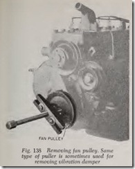
Fig. 138 illustrates a pulley being removed by a screw-type universal puller. The puller is attached to the pulley by the two cap screws which are threaded into two holes in the pulley. The long eenter screw is then turned clockwise until its end butts against the crankshaft. Further turning of the screw forces the pulley off the shaft.
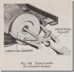
Another universal puller, called the clamp type,is illustrated in Fig. 139. The two hooked clamps are slipped behind the rim of the damper; turning the center screw pulls the damper off the crank shaft.
A lifter bar, Fig. 136, may be used to pry off the damper or pulley if it is not on too tight.
If the lower edge of the damper or pulley extends below the frame front cross member, it may be necessary to unfasten the front engine mountings and jack up the engine until the cross member no longer interferes. Usually the engine is raised by means of a jack placed under the front end of the oil pan. If such a procedure is neces sary, the oil pan should be protected from damage by placing a board or wooden block between the pan and the head of the jack.
With the foregoing remarks digested, the gen eral procedure, therefore, for removing a timing case cover is as follows:
1. Remove radiator, if necessary.
2. Remove vibration damper or pulley.
3. Remove oil pan if it interferes with taking off the cover.
4. Remove water pump if it or any other units interfere with the work.
5. Remove the cap screws which fasten the cover to the engine block. If any of the cap screws are longer or larger than the others, note which holes they come from and be sure to put them back where they belong when installing the cover.
On some engines, note that the timing case cover is not bolted directly to the cylinder block but instead is bolted to a front end plate which in turn is bolted to the block. Fig. 135 shows the construction used on Studebaker 6-cylinder en gines. Note that there is a gasket between the plate and the block as well as between the plate and the timing case cover.
The front end plate rarely if ever needs to be removed unless the gasket between it and the block starts to leak oil, in which case a new gasket should be installed.
Installation
Clean off all remnants of the gasket stuck to the timing case cover and the cylinder block (or front end plate). Use a suitable solvent if necessary to loosen the gasket material and scrape the surfaces clean. If the timing case cover is sheet steel in stead of a casting, note whether the flange is bulged around the bolt holes. Such “dents” may occur if the gasket material is soft or if the bolts were previously drawn up too tight. Smooth out the dents with a hammer. Failure to do so may result in oil leakage when the cover is re-installed.
Before installing the cover gasket, coat both sides of the cover with a cement made for the purpose. Then paste the gasket against the front end plate or cylinder block, being careful that all bolt holes in the gasket accurately register with the bolt holes in the block.
Sometimes the gasket consists of more than one piece, but if so the procedure is just the same. Also note that if the gasket is continuous but if not all of it touches the cylinder block, Fig. 140, tear off the piece which is not in contact with the block.
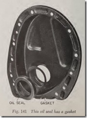
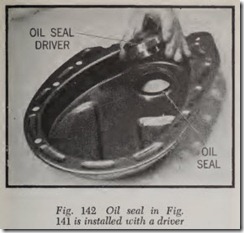
Before installing the cover, a new oil seal should be inserted in its pocket in the cover, Fig. 141. Depending on the fit between oil seal and pocket as well as on the construction of the oil seal, there
are three customary methods of installing the seal: It may be cemented in place; if it cannot be pressed in by hand a suitable driver or drift should be used such as shown in Fig. 142. An appraisal of the old oil seal should indicate which method to use in installing th e new one.
The new oil seal, of course, should be identical with the one removed. If it is a felt seal it should be soaked in engine oil for 30 minutes before seating it in the cover.
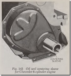
Instead of using th e vibra tion damper to align the oil seal and cover, a special sleeve made for the purpose may be used . Fig. 143 shows the tool made for Chevrolet 6-cylind er engines.
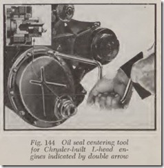
Fig. 144 shows a special centering tool for Chrysler-built L-h ead engines. Install the cover and tighten the cap screws only enough to hold cover in place. Thread the tool on the crankshaft and turn it up finger tight. Then tighten the cap screws gradually and at th e same time draw up on the nut on the tool gradu ally. When all screws are tight, remove the tool and install vibration damper.
