Introduction
VALVE SYSTEM PARTS
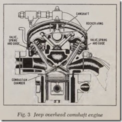
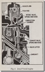
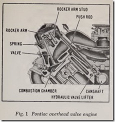
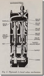
The names of the various parts in the valve system will be found on the numerous illustrations in this chapter. The basic parts, however, are indicated in Figs. 1 to 5. A more detailed description follows:
Valve head is the top portion of the valve, sometimes called the valve crown.
Valve face is the beveled portion of the valve head which contacts the cylinder block when the valve is closed ( L-head engines), or which con tacts the cylinder head on overhead valve engines.
Margin is the narrow rim on the circumference between the valve face and the top of the valve, Fig. 2. Valve seat is the beveled surface on the cylinder block or cylinder head which the valve face contacts when the valve is closed. On L-head engines the seat is in the block; on overhead valve engines the seat is in the cylinder head.
Valve stem is the round, rod-like piece attached to the valve head.
Valve stem guide is the part through which the valve stem operates. These guides are usually a separate piece resembling a bushing and pressed in the guide hole. However, in some modern overhead valve engines the guides are machined holes bored directly in the cylinder head.
Valve stem clearance is the clearance between the valve stem and its guide. A certain amount of clearance is necessary between these parts to pro vide free running (without binding) when the engine is operating. This clearance is also called valve guide clearance or valve stem-to-guide clearance.
Valve operating clearance is the clearance be tween the tip of the valve stem and the valve lifter tappet. This clearance is necessary so that the valves will fully close when the engine is operat ing with the parts expanded due to heat. This clearance is also called tappet clearance, valve clearance, or valve lash.
Valve spring is used to pull the valves closed after they have been opened by the cams on the camshaft.
Valve spring retainer, as the name implies, retains the valve spring on the valve.
Valve lock or key is the device which keeps the valve spring and its retainer in place on the valve.
Valve chamber is the space in which the valve springs are located on L-head engines.
Valve cover on which the valve chamber is enclosed is called a valve cover plate, valve cham ber cover or just valve cover.
Rocker arm cover is the cover which encloses the rocker arms on overhead valve engines.
Push rod cover is the cover which encloses the pu sh rods.
Push rods are long rods which operate between the valve lifters and the rocker arms.
Valve lifters or tappets are the parts which transmit the motion of the cam to the valve stem on L-head engines, or to the push rod on overhead valve engines. These devices are properly called valve lifters because that is exactly what they do. The word tappet, although still used by some car manufacturers, originally meant the adjusting screw which screws into the top of the valve lifter. To be more precise, therefore, the body of the assembly is called the valve lifter while the screw which actually contacts the valve tip or push rod may be called the tappet screw. However, inas much as many modern engines have hydraulic valve lifters which require no screw for adjust ment purposes the term valve lifter seems more appropriate.
Valve lifter guide is a machined hole bored in the cylinder block in which the valve lifter op erates.
Mushroom type valve lifter has a base which is considerably larger than the guide hole in which it operates, Fig. 2.
Barrel type valve lifter is one which has the same diameter throughout its length.
Rocker arm, which is pivoted on a hollow rocker arm shaft, is operated on one side by the push rod to open the valve and on the other side by the valve spring which closes the valve. Some recent engines do not have rocker arm shafts; instead each rocker arm pivots on a stud, Fig. 1.
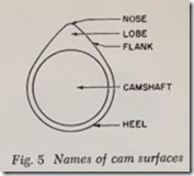
Cams on camshaft consist of two portions, Fig. 5, the base circle or heel and the lobe which juts out from the heel. It is the lobe which opens the valve. The lobe consists of a rounded nose and two flanks .
VALVE OPERATING CONDITIONS
In order to diagnose valve troubles intelligently and then cure them it is necessary to have a clear idea as to the conditions und er which the valves work.
To begin with, it is most important to realize that in a typical engine the valves are open about one-third of the time and closed two-thirds of the time. Each valve opens and closes every two revolutions of the crankshaft.
Theref ore, at 60 mph there are about 1500 openings and closings per mile or per minute, which means that each valve in a typical engine is open 1/75 second and closed 2/75 second. This gives an idea how fast the valves move.
But it is of equal importance to realize that these valves are closed 40 minutes in each hour of operation and open 20 minutes, regardless of what the car speed is, or how fast the engine runs. These thoughts should be particularly helpful in understanding the temperature conditions under which the valves operate.
Impelled by strong springs, the valves , when they close, strike their seats with violent blows. The force of these blows increases with engine speed because the cams are rotating faster. When the engine is running fast, the collision of a valve with its seat may represent a force of several hundred pounds. The blows should be thought of as hammer blows which are no different in prin ciple from hammer blows striking an anvil. The cam which operates the valve is provided with opening and closing ramps. The closing ramp slows down the final closing of the valve and reduces the force of the hammer blows but even so these blows are still sharp.
VALVE OPERATING CLEARANCE
In order to maintain properly cooled valves it is desirable that the valves be set according to the clearances recommended by the car factory. The more the clearance is reduced below the correct figure the longer the valve r emains open and likewise the shorter the tim e that it rests on its cool seat. In explanation , it should be obvious that the less the clearance the sooner the valve will be opened and the hter it will be closed. Thus an exhaust valve is exposed to hot exhaust for a longer period and similarly it sits on its cool seat for a shorter period. Both effects increase the temperature of the valve and may raise the tem perature beyond the danger point especially if there are other operating conditions which in crease the valve tmperature above normal.
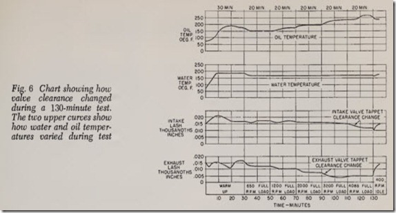
Valve clearance grows less as the engine warms up. Just exactly how the clearance varies in a typical engine is shown in a 130 minute test which was made by Thompson Products, Inc. Fig. 6 shows how intake and exhaust valve clearance varied during the test. The engine was allowed to idle for 20 minutes and then it was operated at full throttle for 20 minutes at each of the follow ing speeds: 650, 1200, 2000, 3200, 4088 rpm. After 130 minutes the engine was allowed to idle again.
The valve clearance when the engine was cold was .015″ for both intake and exhaust. After the engine had idled for 10 minutes the vertical ex pansion of the block increased the clearance to
.020″. From 20 to 100 minutes the intake clearance was just a trifle more than .015″. Exhaust valve clearance was normal after 10 minutes idling; decreased to .011″ after 20 minutes because of stem expansion; was .017″ at 30 minutes because of block expansion counteracting stem expansion. At this point the block reached its maximum expansion but the exhaust valve temperature con tinu ed to increase as engine speed was raised. Therefore the continued expansion of the valve stem reduced the clearance to a minimum of .005″ during the 100 to 130 minute interval.
Oil temperature reached a maximum of more than 250 degrees at 135 minutes. Water tempera tur e was a maximum of 180 degrees during the latter part of the idling period and then dropped to 170 degrees during the rem ainder of the run.
The test just described emphasiz es the impor tance of correct valve clearances because in this particular engine the exhaust valve clear ance is reduced to .005″ when operating at high speed at full throttle. If th e valves had been incorrectly adjusted in the first place to .010″ or less they would have leaked at full load.
Causes of Valve Troubles
VALVE LEAKAGE
Valve leakage involves two things: ( 1) Leaks caused by mechanical defects in the valve system and ( 2) leaks due to deposits.
To simplify this discussion we shall assume temporarily that all the parts in the valve system are clean, which means that they are not covered with deposits of any description such as carbon, gummy oil, and so forth. With this assumption, if a valve is to be leak-proof, the following mechani cal conditions must be present:
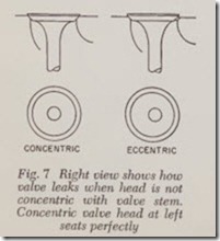
Valve face must be circular and concentric with stem. The face, obviously, must be concentric with the stem if the valve is to fit snugly into the valve seat with absolutely leakproof contact. Fig. 7 shows how a concentric valve head fits tight against its seat and also how an eccentric valve head fails to seat perfectly.
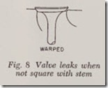
Valve head must be square with stem. Obvi ously the valve will leak if the head is not at right angles to the stem, Fig. 8.
Valve stem must be straight. A valve stem with even a slight kink in it will retard valve closing by binding in the guide, Fig. 9. And the kink may be sufficient to cause the valve to stick open.
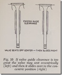
Valve guide must be true and clearance correct. If valve stem-to-guide clearance is too little, the speed of the valve closing may be retarded or there may be insufficient clearance for an ade quate oil film. If valve clearance is excessive, the guide is no longer able properly to guide the valve onto its seat. The extra clearance permits the valve stem to shuttle crosswise, with the result that the valve head may be somewhat eccentric to the seat when it makes contact, as shown in the left dia gram, Fig. 10. Because of the conical f ace and seat this condition is immediately rectified as shown in the right diagram. In other words, the conical faces force the valve to seat tightly but n ote that it takes an appreciable instant for the valve to slide sideways into its fully seated position. Thus valve closing is delayed. Prompt valve closing is ex tremely important for maximum exhaust valve life. Delayed closing increases the temperature.
Eccentric valve seating because of too much guide clearance causes extra wear on both valve face and seat because the brunt of the powerful impact of valve closing is taken by a small portion of the circumference instead of by the whole cir cumference.
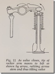
On overhead valve engines, excessive valve stem-to-guide clearance will not only cause the troubles just described but also it should b e real ized that the wiping action of the ro cker arm, acting on the tip of the valve stem, may cock the valve in its guide and cause leakage, Fig. 11.
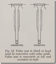
Fig. 12 shows that if the valve seat is concentric with the valve guide, the valve will close tight, as indicated at the left, whereas if the valve seat is eccentric the valve will be held off its seat and will leak, Fig. 12 right. However, if valve guide clear ance is sufficient to permit it, the valve will slide diagonally to give tight seating. The action is the same as illustrated in Fig. 10.
Valve spring strength must be correct. If valve springs have become weak, valve closing will be delayed, especially at full engine speed, at which time a full strength spring is required to make the valve and valve lifter follow the cam. A weak spring lacks the force to close the valve promptly. Prompt closing is essential for maximum valve life as well as for maximum power. Springs that are too strong will cause undue wear on the valve mechanism because their extra strength causes more powerful battering of the valve against its seat. Likewise cam and valve lifter wear are increased.
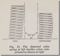
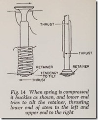
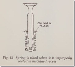
Valve springs must be straight. A valve spring which does not stand perpendicular to a flat sur face will bulge as shown in Fig. 13 when the valve is open. This places a side thrust on the valve stem and gradually wears the guide as shown in Fig. 14, preventing valve from closing tight. It should also be obvious that if a deformed valve spring is installed on a valve with a worn guide, the valve will start leaking immediately because the spring cocks the valve to one side. If the valve spring is improperly seated, it will cause the same troubles as mentioned above. Fig. 15 shows that the top coil of the spring is not resting in the machined recess at one side.
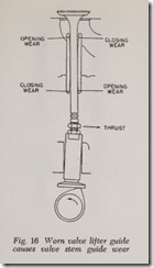
Valve lifter guide clearance must be correct. On L-head engines, if the clearance between the valve lifter and its guide is excessive, the lifter will be cocked as shown in Fig. 16 each time the valve is opened. At this moment, the lifter thrust will try to cock the valve stem in the opposite direction as shown. When the valve is closing, all these forces are reversed. Thus a loose valve lifter eventually wears the valve guide into a bell-mouthed shape at top and bottom. The worn valve guide inter feres with accurate seating of the valve and thus its hours of leak-proof service are reduced.
Valve guide wear caused by rocker arms. On overhead valve engines, the tip on the valve stem and the tip of the rocker arm which contacts the valve stem should be smooth and should make good contact with each other. When the rocker opens and closes the valve, it creates a side thrust (as shown in Fig. 11), and if the contacting surfaces are not smooth, the side thrust will be excessive and the valve guide will gradually be worn as illustrated. This wear cocks the valve and prevents it from seating perfectly.
Correct valve operating clearance. In connec tion with the preceding items, it is assumed that the valve operating clearance is correct. If the clearance is too great, an extra strain is put on the valve parts during valve opening. Likewise, when the valve closes it may batter against the seat with blows of greatly increased intensity. Too much clearance also eliminates the beneficial ramps on the cam.
If the clearance is too little, the valve will be held off its seat for a longer period than necessary. And if there is no clearance at all the valve will leak because it is unable to close tight.
