GENERAL MOTO RS CCS
Controlle d Combustion System
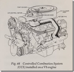
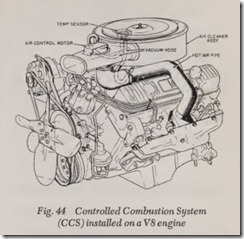
The C.C.S. system, Fig. 44, is designed to keep the air entering the carburetor at approximately 100 deg. F. or above so that the carburetor can be calibrated to operate leaner without aff ecting engine performance, provide improved fuel econ omy, eliminate carburetor icing and improve en gine warm-up.
Because of the leaner carburetor calibration, the ignition timing at idle must be retarded. This is done by means of a “ported” vacuum advance, with the vacuum take-off just above the throttle plate(s), so that there is no vacuum advance at closed throttle but there is advance as soon as the throttle is cracked slightly. Ignition timing is set at or near TDC and centrifugal advance does not start until approximately 1000 rpm.
Thermo Vacuum Switch
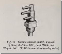
Because of the increased possibility of engine overheating at idle with the C.C.S. calibration, the thermo vacuum switch, Fig. 48, is added to the system on some engines. This switch senses engine coolant temperature and, if temperature reaches 220 deg. F., the switch valve moves to allow manifold vacuum to reach the distributor, to ad vance the timing and allow the engine to run cooler.
Idle Stop Solenoid
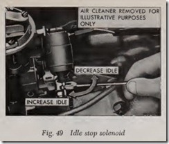
Most cars equipped with the Controlled Com bustion System have an idle stop solenoid mounted on the carburetor, Fig. 49, to prevent engine operation after the engine is shut off (die seling). Dieseling is prevalent with the CCS system, especially with automatic transmission because of th e retarded ignition timing and high er operating temperature of the engine. Idle speed is higher with automatic transmissions.
The solenoid eliminates this dieseling by fully closing the throttle valve ( s) when the ignition is turn ed off .
Wh en the ignition switch is turned on, the solenoid coil is activated and the plunger is driven to its full extended position. The plunger acts on the throttle valve lever and sets the throttle valve(s) in a position to achieve spceified idle rpm.
When the ignition is turned off, the solenoid is de-energized and the plunger retracts into the solenoid, causing the throttle valve( s) to close to a position controlled by the low idle adjusting screw. At this point the throttle valve ( s) is open only enough to allow the engine to run at a much lower rpm. This lower setting keeps the throttle valve ( s) from completely closing and scuffing the throttle bore ( s).
The lower idle speed setting is made with a set screw when the solenoid is electrically discon nected. The setting for normal idle speed is ad justed, with the solenoid energized, thro h he hex screw in the plunger and/or by repos1homng the solenoid in its mounting clamp.
NOTE: To set the solenoid while starting a hot engine, the accelerator pedal must be depres ed approximately one third its travel. When startmg a cold engine, however, the accelerator must be fully depressed to set both the choke and the solenoid.
CAUTION: Unburned gases emit undesirable amounts of hydro-carbons, predominantly during idle operation. One would naturally thin that if the idle mixture is made as lean as possible, ex haust emission would be reduced. This is true up to a point. However, if the idle mixture is made too lean, the hydro-carbon content may increase ab ve acceptable limits. The amount of carbon monoXIde exceeds acceptable limits when idle mixtures are too rich. Conversely, the hydro-carbon content exceeds acceptable limits if the idle mi ture is to_o “lean.” Consequently, proper idle adJustment IS essential.
TRANSMISSION CONTROLLED SPARK (TCS)
American Motors
This system is designed to provide vacuum spark advance during high gear operation and certain engine conditions. The resultant is a lower peak combustion pressure and temperature during the power stroke, significantly reducing exhaust emissions.
Basically the system incorporates an ambient temperature override switch, solenoid vacuum valve, solenoid control switch and in some sys tems a coolant temperature override switch.
The ambient temperature override switch, senses ?.mbient temperatures and completes the electrical circuit from the battery to the solenoid vacuum valve when ambient temperatures are above 63° F.
The solenoid vacuum valve is attached to the intake manifold. When the valve is energized, carburetor ported vacuum is blocked and the distributor vacuum line is vented to atmosphere through a port in the valve, resulting in no vacuum advance. When the valve is de-energized, ported vacuum is applied to the distributor resulting in normal vacuum advance.
The solenoid control switch, located at the trans mission, opens or closes in relation to car speed for automatic transmission equipped cars or gear range manual transmission equipped. At speeds above 34 MPH on automatic transmission equipped cars, high gear on manual transmission equipped. car , the switch opens and breaks the ground cucmt to the solenoid vacuum valve. At speeds under 25 MPH on 1971-73 models or 35 MPH on 1974-76 model automatic transmission equipped cars, low er gear ranges manual transmission equipped, the switch closes and completes the ground circuit to the solenoid vacuum valve.
On automatic transmission equipped vehicles, the switch is automatically operated by the speed ometer gear speed on 1971-73 models or transmis sion governor oil pressure on 1974-77 models. On manual transmission vehicles, the switch is man ually operated by the shifter shaft.
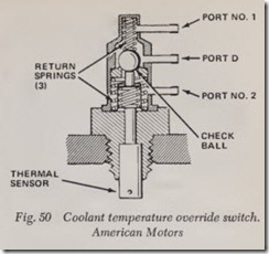
The coolant temperature override switch, Fig.50, is threaded into the thermostat housing on V8 engines or into the left rear side of the cylinder block on six cylinder engines. Its purpose is to im prove driveability during the warm-up period by providing full distributor vacuum advance until the engine coolant has reached 160° F. on V8 en gines and 1975-76 six cylinder engines or ll5° F. on 1974 California six cylinder engines with manual transmission and 1977 Matador with VS-360. The switch incorporates a thermal unit which reacts to coolant temperatures to route either intake mani fold or carburetor ported vacuum to the distribu tor vacuum advance diaphragm.
The CTO system may be used in place of or in conjunction with the TCS system depending upon application.
General Motors
This system is designed to provide vacuum spark advance during high gear operation only. The resulting ignition timing in the lower gears significantly reduces exhaust emissions.
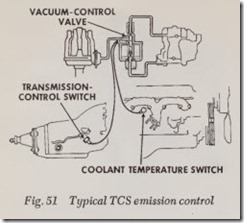
Basically, the TCS system consists of a vacuum control valve, transmission control switch and a coolant temperature switch. The valve controls the vacuum signal to the distributor vacuum ad vance unit in response to a signal from either switch, Fig. 51.
The vacuum control valve is of solenoid design and is installed in’ the vacuum line between the carburetor and the distributor. When energized by the transmission control switch, the valve blocks the vacuum source and vents the advance unit through the carburetor air horn.
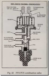
When the engine is cold, and in some units when the engine temperature exceeds 210° F, the coolant temperature switch overrides the system and provides fu11 manifold vacuum to the advance unit, advancing timing and in turn lowering engine operating temperature. This switch operates through a relay mounted on the firewall. Some systems use combination TVS-TCS valve, Fig. 52, to provide system over-riding vacuum to the ad vance unit.
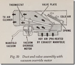
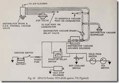
A TCS system change on mid-year 1973 and all 1974 Pontiac models (vehicles manufactured after March 15, 1973) will incorporate the following re visions, Fig. 39: A Start-up Relay Switch supplies full advance (ported advance on manual transmis sion vehicles) in any gear for 20 seconds after en gine start.
A Distributor Vacuum Spark Thermal Valve on 1973 models or Distributor Spark-EGR Thermal Vacuum Switch on 1974 models, sensing air-fuel mixture temperature, provides full advance in any gear when the mixture temperature is below 62° F.
When air-fuel mixture temperature rises above 62°F., the thermal valve closes, shutting off vacuum.
In turn to provide vacuum advance, the distributor must be energized, depending on condition, by the TCS Switch, Cold Feed Switch or the Hot Coolant Switch.
The TCS Switch grounds the distributor solenoid in high gear on all applications and in reverse gear on 1974 vehicles equipped with automatic trans missions only when the Cold Feed Switch is closed. The Cold Feed Switch, depending on application, closes when cylinder head temperature reaches 125°, 140° or 155° F. Regardless of TCS Switch position, the Hot Coolant Switch grounds the dis tributor solenoid when coolant temperature is over 240° F.
On some models, a Distributor Vacuum Spark Delay Valve is installed between the distributor solenoid and distributor. This valve restricts the rate of initial vacuum supplied to the distributor, full vacuum will be supplied gradually.
The Time Relay is an electrical on-off type switch. When the coil is energized, it starts heating the bi-metal strip and opening the normally closed relay points within 20 seconds after the ignition switch is turned on. If for some reason the ignition key is left in the “ON” position and vehicle is not started within 20 seconds and the relay completes its “countdown,” vacuum advance will be blocked off until the relay has cooled off.
NOTE: Once the relay has run one cycle (about 20 seconds), after the key has been turned on, the relay must cool off before it will reactivate, even if the key is switched “OFF” and then turned “ON” again.
GENERAL MOTORS CEC
Combined Emission Control System
This system is designed to provide vacuum spark advance during high gear operation only, as does the TCS system, but the CEC solenoid vacuum switch also regulates curb idle and high gear deceleration throttle positions, further reduc ing emissions.
The CEC system consists of a vacuum control solenoid valve, transmission control switch, coolant temperature switch and a time-delay relay.
When the solenoid is in the non-energized posi tion, vacuum to the distributor vacuum advance unit is shut off and the distributor is vented to the atmosphere through a filter at the opposite end of the solenoid. When the solenoid is ener gized by one of the switches or the relay, the vacuum port is uncovered and the plunger is seated at the opposite end, shutting off the clean air vent. This routes vacuum to the distributor. The solenoid is energized in high gear by the transmission switch. The coolant temperature switch overrides the transmission switch to ener gize the solenoid and provide vacuum advance be low 82° F., and the time-delay relay is incorpo rated into the circuit to energize the solenoid for approximately 15 seconds after the ignition key is turned on.
When the solenoid plunger is in the non-ener gized position, it allows the throttle to close to the curb idle setting. When the solenoid plunger is in the energized position , it keeps th e throttle open to the high gear deceleration position which controls hydrocarbon emission .
GENERAL MOTORS SCS
Speed Controlled Spark
This system is essentially the same as the TCS system except th at here the vacuum spark advance is controlled by the vehicle’s speed rath er than the gear position of the transmission .
The SCS system consists of a vacuum advance solenoid valve, a speed sensing switch and a temperature switch. The vacuum control valve is installed in the vacuu m line b etween the carbure tor and the distribut or. When en er gized, this valve cuts off vacuum to the distributor. The speed sensing switch de-energizes the vacuum control valve at speeds above 38 mph allowing normal vacuum spark advance. Abnormal operating tem peratures (below 85 degrees F. and above 220 degrees F.) will cause the tempera ture switch to de-energize the vacuum control valve, over-riding the speed sensing switch .
GENERAL MOTORS EGR
Exhaust Gas Recirculation
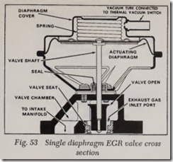
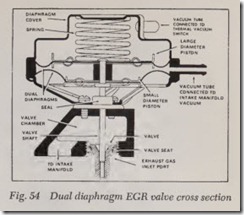
This system, Figs. 53 and 54, is used to reduce oxides of nitrogen emissions at the engine’s ex haust. This is accomplished by introdu cing exhaust gases into the intake manifold at throttle positions other than idle. It consists of an E.G.R. valve mounted on a special intake manifold. The exhaust gas intake port of the E.G.R. valve is connected to the intake manifold exhaust crossover channels where it can pick up exhaust gases.
As the throttle valves are opened and the engine speeds up, a vacuum is applied to a vacuum dia phragm in the EGR valve through a connecting tube. When the vacuum reaches approximately 3″ Hg., the diaphragm moves upwar d against spring tension and is in the full-up position at approximately 7″ to 8″ Hg. of vacuum . This dia phr agm is connected by a shaft to a valve which closes off the exhaust gas port. As the diaphragm moves up, it opens the valve in the exh aust gas port which allows exhaust gas to be pulled into the intake manifold and enter the cylinders. The exhaust gas port must be closed dming idle as the mixing of exhaust gases with the fuel air mixture at this point would cause rough running.
The dual diaphragm EGR valve, Fig. 54, is de signed to provide increased exhaust gas recircula tion rates when engine loads increase.
NOTE: Manifold vacuum is used as the signal to indicate the engine load.
The valve is similar to the single diaphragm valve except that a second diaphragm has been added to the valve and is connected to the upper diaphragm, with a spacer, thus both diaphragms move together. A manifold vacuum signal is ap plied to the volume between the two diaphragms. The upper diaphragm has a larger diameter piston than the lower diaphragm, therefore the load caused by the manifold vacuum between the two diaphragms aids the spring load. Thus as the en gine load increases and manifold vacuum decreases the combined load of the spring and the vacuum chamber are reduced allowing the valve to open further for a given EGR vacuum signal.
Therefore, for high intake manifold vacuums (such as cruising), the opening is less than for low manifold vacuums obtained during accelerations. The valve now is capable of providing more re circulation on accelerations where loads are higher and the tendency to produce NOx is greater.
Exhaust Back Pressure Transducer Valve
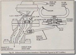
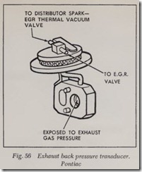
Figs. 55 and 56.-This valve, used on some 1974 77 vehicles, modulates EGR Row according to engine load. The device consists of a diaphragm valve, a spacer and a metal tube.
The EGR system, when equipped with a back pressure transducer valve, obtains a vacuum sig nal at the carburetor spark port and not at the EGR port. This vacuum is modulated by the trans ducer and, in turn activates the EGR valve.
When exhaust back-pressure is relatively high, as during acceleration and some cruising condi tions, exhaust back-pressure traveling through the metal tube overcomes spring tension on the dia phragm within the back-pressure transducer valve, and closes the valve atmospheric vent.
With the back-pressure transducer valve no longer vented to atmosphere, the vacuum signal now passes through the back-pressure transducer valve, and the EGR valve. When vacuum signals the EGR valve, exhaust gas recirculation com mences.
When exhaust back-pressure is too low to over come diaphragm spring tension, the vacuum signal is vented to atmosphere and does not pass through to the EGR valve. With no vacuum signal applied to the EGR valve, exhaust gas does not recirculate.
Vacuum Bias Valve
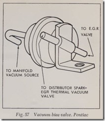
This valve, Fig. 44, used on some California 1974-75 Pontiac vehicles, is located between the EGR valve and the distributor spark-EGR thermal vacuum valve. At high manifold vacuum conditions (such as cruising), the VBV decreases EGR flow and in turn, acts to reduce surge. When NOx for mation is high and manifold vacuum is low as during acceleration, the VBV does not reduce EGR How.
.An EGR system change on all mid-year 1973 V8 and 1974-75 six cylinder Pontiac models (vehi cles manufactured after March 15, 1973) will in corporate a new EGR Thermal Vacuum Valve which senses engine coolant temperature. This thermal valve, located between the carburetor and EGR valve, controls vacuum o the EGR valve. When coolant temperature is below 95° F. on 1973 models or 100° F. on 1974-75 models, the thermal valve isolates the EGR valve from the vacuum source, therefore eliminating exhaust gas recircula tion. When coolant temperature is above 95° F. on 1973 models or 100° F. on 1974-75 models, the thermal valve opens and allows vacuum to actuate the EGR valve, allowing ported recirculation. On 1974-75 Pontiac vehicles equipped with V8 engines, the EGR Thermal Vacuum Valve and the Distribu tor Spark Thermal Vacuum Valve is incorporated into one assembly, Fig. 58. This Distributor Spark EGR Thermal Vacuum Valve senses air-fuel mix ture temperature. This thermal valve is located be tween the EGR Valve and its vacuum source. The valve prevents actuation of the EGR valve when air-fuel mixture temperature is below 62° F. When air-fuel mixture temperature exceeds 62° F., the valve opens and allows vacuum to activate the EGR valve.
