Check Valves
1. Check valves should be inspected whenever the hose is disconnected from the valve or whenever valve failure is suspected .
Note that if an air pump shows any signs of the presence of exhaust gas, this is an indica tion that the check valve has failed.
2. Orally blow through the check valve (toward the air manifold) then attempt to suck back through the check valve. Flow should be in one direction only, toward the air manifold.
3. To replace a check valve, disconnect the pump outlet hose at the check valve. Rem ove the valve from the air manifold, taking care not to bend or twist the manifold.
Diverters or Air By-Pass Valve
1. Check condition and routing of all lines, espe cially the signal line (the small diameter hose between intake manifold and the diverter valve). All lines must be secure, without crimps, and not leaking.
2. Disconnect signal line at valve. A vacuum signal must be available at the valve with the engine running.
3. With engine warmed up to operating temperature and throttle at curb’idle, no air should be escaping through the valve’s muffler. Open and quickly close the throttle. A momentary blast of air should discharge through the valve’s muffler for at least one second. If it does not, and there is a good vacuum signal at the valve, then the valve is defective and should be re placed.
CAUTION: Although sometimes similar in ap pearance, these valves are designed to meet the particular requirements of individual en gines. Therefore be sure to install the right valve for the engine being worked on.
4. To replace a valve, disconnect the vacuum signal line and valve exhaust hose or hoses.
5. Remove diverter or air by-pass valve from pump, and the muffler from the valve assem bly, noting the angle of attachment.
6. Install muffler to new valve at previously noted angle.
7. Install diverter or air by-pass valve to pump or bracket with new gasket.
8. Install outlet and vacuum lines and check system for leaks.
Mixture Control or Backfire By-Pass Valve
1. Check condition of all lines, especially the sig nal line. A defective signal or outlet line will cause malfunctioning of the mixture control or back£re by-pass valve.
2. Disconnect pump-to-valve inlet hose at pump.
3. A leaking valve will be indicated by an air gushing noise coming from the hose. Place palm of hand over hose. Little or no pull with a gradual increase is normal. If an immediate strong pull is felt, or air noise is heard, the valve is defective and must be replaced.
4. Open and close the throttle rapidly. Air noise should be evident and then gradually decrease. If air noise is not evident, or if the valve is noisy, it should be replaced.
To replace this valve, disconnect the signal line, air inlet and air outlet hoses, and remove valve.
6. Install new valve and connect hoses.
CAUTION: Like the diverter or air by-pass valve, these valves are designed to meet par ticular requirements of individual engines. Therefore be sure to install the correct valve for the engine being worked on.
Air Injection Tubes
There is no periodic service or inspection for these parts. However, whenever the cylinder head is removed from in-line engines, or exhaust mani folds from V-8 engines, inspect the tubes for car bon build-up and warped or burned tubes. Re move any carbon with a wire brush. Warped or burned tubes must be replaced.
1. To replace a tube, remove carbon, and using penetrating oil, work tube out of cylinder head or exhaust manifold. Then install new tube.
Air Injection Pump
1. Accelerate engine to about 1500 rpm and ob serve air flow from hose or hoses. If flow in creases as engine speed rises, the pump is operating properly. If flow does not increase with engine speed, or if there is no air flow, proceed as follows:
2. Check for proper drive belt tension.
3. Check for leaky pressure relief valve. Air may be heard leaking with the pump running.
It is important to remember that the air pump system is not completely noiseless. Under normal conditions noise rises in pitch as engine speed increases. To determine if excessive noise is the fault of the system, operate the engine with the pump belt removed. If the excessive noise disappears with the belt removed, proceed as follows:
4. Check for proper installation of the relief valve silencer (if equipped).
5. Check for seized air pump.
6. Check hoses, tubes, air manifolds and all con nections for leaks and proper routing.
7. Check carburetor air cleaner for proper installation.
8. Check air pump for proper mounting.
9. If none of the above conditions exist and the air pump is excessively noisy, remove and re place the pump unit.
10. To replace the pump, disconnect hoses at pump and remove pump pulley, unfasten and remove pump.
11. Install new pump with mounting bolts loose.
Then install pump pulley and drive belt.
12. Adjust drive belt tension and connect hoses at pump.
Pressure Relief Valve
When the pressure relief valve is incorporated in the diverter or air by-pass valve the complete valve must be replaced. If the relief valve is in the pump, proceed as follows:
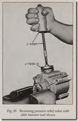
1. Pull relief valve from pump, Fig. 25.
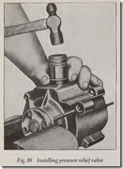
2. Using a 15/16″ socket, Fig. 26, tap relief valve into housing until valve shoulders on housing. Use extreme care to avoid distorting housing.
NOTE: Various length pressure setting plugs de signed for the particular requirements of the ve hicle being worked on determine the pressure required to open the relief valve. Usually the pressure setting plugs are color-coded. To remove the pressure setting plug, carefully unlock the legsfrom the inside surface of the relief valve with a small screwdriver. To install the plug, carefully push it into the relief valve until the legs lock. If a pressure setting.plug is to be re-used, be sure the leg angles are sufficient for the plug to lock in place.
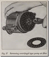
Centrifugal Pump Filter, Fig. 27
1. To replace the centrifugal type filter, remove drive belt and pump pulley. Pry loose outer disc of filter fan, being careful to prevent frag ments from entering the air intake hole.
2. Install the new filter by drawing it on with the pulley and pulley bolts. Do not attempt to install a filter by hammering it or pressing it on.
3. Draw the filter down evenly by alternately tightening the bolts. Make certain that the outer edge of the filter slips into the housing. The slight amount of interference with the housing bore is normal.
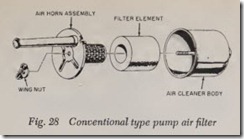
Conventional Type Filter, Fig. 28
Remove and replace the air filter element as suggested by the illustration. The element is not cleanable. It must be replaced. Position the assem bled air horn and filter element in the air cleaner body, being sure the tang is fitted into the slot .
NON-AIR-PUMP SYSTEMS
These are the systems which improve the quality of the exhaust gases by bmning a proportion of them in the cylinders. This is accomplished by modifications to the carbmetor, distributor and combustion system. Also by the addition of extra refinements which improve the efficiency of sys tems and improve driveability.
PULSE AIR INJECTION REACTOR (PAIR)
General Motors
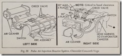
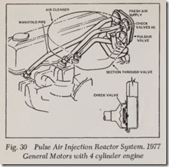
This system, Figs. 29 and 30, utilizes exhaust pressure pulsations to draw fresh air from the air cleaner into the exhaust system.
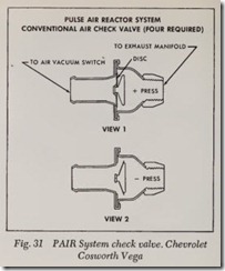
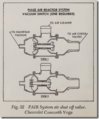
The Cosworth Vega system consists of one air “check valve,” Fig. 31, located on each of the four exhaust manifold legs adjacent to the cylinder head, and a pulse air shut off valve through which filtered air Bows to the check valves.
On all other models, this system uses a series of pipes and check valves in the pulse air valve to route fresh air into the exhaust manifold, Fig. 30.
Engine operation causes a pulsating How of ex haust gasses which are of positive or negative pres sure, depending on whether the exhaust valve is seated or not. If pressure is positive, the disc is forced to the closed position, allowing no air How into the exhaust system. If pressure is negative, the disc will open allowing fresh air How into the exhaust system. Due to the inertia at high engine rpm, the disc fails to follow pressure pulsations. Therefore, the disc will remain closed preventing air flow into the exhaust system.
Throttle closure during deceleration, momen tarily causes air fuel mixtures too rich to burn.
These mixtures, when combined with air will be come combustible, causing after fire. On Cosworth Vega models, a Pulse Air Shut Off Valve, Fig. 32, is used to momentarily divert air from the exhaust system to prevent after fire. This valve is calibrated to close only at vacuums exceeding idle vacuum which occur only during engine overrun. A spring is used to hold the valve open during idle, part throttle and wide open throttle.
