Cell Phones
It Is Now Possible to Do Anything Wirelessly: Talk, Text, Email, Web Browse, Games, Whatever
In this Chapter:
● How the cellular system works.
● Cell phone radio technologies.
● Digital modulation and access schemes.
● Cell phone data capabilities.
● Smartphones, femto cells, MIMO, and location technology.
INTRODUCTION
The cell phone is one of the coolest, most useful, and convenient electronic devices of all time. It also happens to be one of the most complex technically, not only internally but because it is part of the largest communications network in the universe, the telephone system. The reason for a separate chapter on this topic is not only because of the advanced wireless technology involved, but also its importance to all of us personally and to the national economy. Since practically everyone has a cell phone today, it plays a huge role in our lives. And for you techies out there, it is worthwhile knowing a bit of the details of how phone calls work, how text messages get sent, and how you can now access the Internet via your cell phone.
CAN YOU HEAR ME NOW?
We’ve all said that before. Why? For one simple reason: cell phones are two- way radios with all the usual faults. The cell phone industry usually refers to itself as the wireless industry, but it’s all the same thing—radio. Your cell phone contains a transmitter and a receiver that collectively are called a trans- ceiver. You will also hear them called handsets. People in the industry also call them mobile terminals. Whatever. Because cell phones have to be so small to be practical, they are limited in the amount of power they can transmit and the type of antenna that is practical. Battery drain is a major factor in cell phone design, as you want to get as much talk time as you can on a battery charge. But by limiting the transmit power you automatically minimize the distance
over which the unit will transmit. In any case, communications range is related to power as well as antenna type and orientation. And the typical range of a cell phone is a mile or so, depending on conditions. Take a look at the sidebar to review some of the facts about wireless and radio covered in Chapter 7.
Factors Affecting Range and Reliability to Radio Transmission
Range—The greater the distance between any transmitter and receiver, the smaller the signal. Signal strength varies inversely by the square of the dis- tance between transmitter and receiver.
Power—The higher the power the greater the transmission range. More power translates into increased communications distance up to a point.
Antenna gain—Some antennas focus the signal in a specific direction. Doing so gives the antenna gain, meaning it multiplies the power of the transmitter and the signal strength at the receiver.
Environment—Cell phones and any other microwave wireless device always transmit farther in clear open space. The ideal is direct line of sight (LOS), meaning that the two antennas can “see” one another. While cell phones don’t have to have such a clear path to work, they always work better if they do. Environment also means transmitting from inside a building. Yes, radio waves do pass through walls and other obstructions but as they do they lose considerable strength as they encounter obstacles. Walls, ceilings, floors, and any other obstructions greatly attenuate (make it smaller) the radio signal. So if you are inside a car, shopping mall, office, or airplane, your signal strength loses over half its strength and that severely restricts your range.
Height—Getting your cell phone to the highest possible point will greatly increase transmission distance. This helps the line of sight effect so important to reliable transmission. Getting higher typically isn’t practical, but almost nothing helps more than height, especially outside.
Receiver sensitivity—This means how much gain the receiver has. High gain translates into greater range.
Multipath—Whenever you are transmitting in an environment with lots of obstructions, your signal will bounce off many objects and be reflected. Some reflected signals will get lost and never get to the receiver. Others will bounce off objects that will ultimately direct them to their intended destina- tion. These reflected signals will be delayed in time. Depending on factors such as operating frequency and distance traveled, these signals could arrive in phase and actually boost reception level. Or they could arrive out of phase and literally cancel the more direct signal that arrived earlier.
Noise—Don’t forget that noise also affects communications distance and reli- ability. See discussion in Chapter 7.
THE CELLULAR CONCEPT
The original designers of the cell phone created a system that helps overcome the range and power problem described in the sidebar. If distances are kept
short, then other limitations in power and environment are offset. The working word here is “cell.” A cell or cell site is one of many transmit/receive stations set up to communicate with individual cell phones. Also known as base stations, these facilities are easily recognized by their tall antenna towers. The small building at the base of the tower houses racks of transceivers that share the big antennas at the top of the tower. Long coax cables carry the signals to and from the antenna. They actually look like pipes going up the side of the tower.
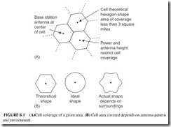
Cell phone systems have dozens to hundreds of cell sites. An ideal design is shown in Figure 8.1A . Each cell represents an area covered by the base station antennas. Cell range and overall coverage are deliberately restricted by antenna height and radiation pattern as well as transmitting power. The hexagon- shaped cells are only theoretical. In reality, the shape of the cell is more circu- lar or rather an irregular circular shape because of antenna characteristics and environmental characteristics that affect the cell shape (nearby trees, buildings, etc.) (see Figure 8.1B).
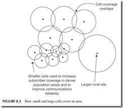
While equal-size cells are desirable and operation more predictable, in the real world, the coverage of each cell depends a great deal on the number of cell phone subscribers as well as the terrain and environment. In large cities with lots of people and buildings, smaller cell sizes are used to increase subscriber capacity and provide the most reliable coverage possible in a given area. Many cities have what are called microcells that may only cover one block or picocells that cover one area of a building. On the other hand, in rural areas and along
major highways, the cell sizes are larger and cover fewer users. The cell cover- age may look more like that in Figure 8.2.
A key feature of the cellular concept is that by keeping the cell sizes small, the frequency channels assigned to cellular service can be reused. One fre- quency may carry different calls if the cell sites are far enough apart and do not interfere with one another. This frequency reuse concept multiplies the overall number of channels available to handle calls.
One other factor to keep in mind is that in most cities, there are two or more cellular companies vying for your business. Each company has its own cellular system with base stations with coverage that overlays the cell coverage of other companies. The competing systems do not interfere with one another because they usually operate on different frequencies with different radio tech- nology, and the cell phones they support know which base stations to talk to.
One other thing: when you are talking on your cell phone, you are talking to only one base station—typically the one closest to you since both the power and range of your handset and that of the base station are limited. If you are moving (such as in a car), you will eventually leave the coverage area of one cell and enter the coverage area of an adjacent cell. You never really know when this happens, but it is a pretty neat technical trick to make this happen. The process of having your call transferred from one cell site to another automatically is called the hand-off.
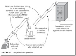
All of the base stations are tied to a central office known as the mobile telephone switching office (MTSO). Many companies simply refer to it as the switch, as its main job is switching between base stations as well as linking to
the main telephone system. The connection between the base stations and the switching station can be by copper cable or fiber optic cable or in many cases by a separate microwave wireless link. This is known as backhaul. If a cell site tower has one or more small “dish” antennas on it you can bet that your signal eventually is communicated back to the switch via another wireless link.
The big job of the MTSO is to control and keep track of everything. It vali- dates you as a subscriber when you turn on your phone and make a call. It keeps track of how many minutes of time you use. And it will get messages from remote switches when you are in the roam mode outside of your usual home subscriber area. The cell phone companies have the ability to use other systems in most major cities and in many foreign countries, so you can use the phone virtually anywhere. Figure 8.3 shows just what goes on when you turn on your phone and make or receive a call.
WHAT’S INSIDE A CELL PHONE?
A cell phone can legitimately be called the world’s most complicated two-way radio. Sure, it is just a transceiver, but it uses practically every radio trick in the book to ensure that you can make your calls reliably anytime with mini- mal hassle. It is a two-way radio that is used just like any other phone you are familiar with. In other words, you do not have to say “over,” “come back,” or any other phrase when you are finished talking and want to listen, as with some two-way radios (CB, family radio, ham radio, aircraft, marine, etc.).
Simultaneous send and receive is referred to as full duplex. All telephones are full duplex. It is easy to do in the wired telephone system but complex and costly to do by radio. Yet, full duplex is what makes cell phones so comfort- able to use. There is none of this “roger and over” stuff. What this means is that your transmitter and receiver are working at the same time. There is more about how duplexing works later.
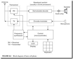
Figure 8.4 shows a general block diagram of what’s in a cell phone. The receiver and transmitter making up the transceiver are obvious and they share the single antenna. The transceiver is usually a single chip. What is not so obvi- ous is what we call the baseband part of the cell phone. Baseband refers to the voice and data to be transmitted or received. In most modern digital cell phones, this is a very complex integrated circuit that handles the translation of voice between analog and digital, modulation and demodulation, and voice compression. All these functions are done digitally by a digital signal processor (DSP) or special DSP circuits in combination with a powerful embedded pro- cessor. This processor or a separate processor handles all the transparent house- keeping jobs of managing the keyboard and the LCD screen as well as the basic control features of the cell system, which also include automatic operating fre- quency selection and automatic power control under the direction of the MTSO via the cell site. The DSP also implements the messaging functions.
What Type of Cell Phone Do You Have?
Shame on you if you don’t know. Well, not really. Actually, it is tough to know just what type of cell phone you have. You can’t tell by looking, even inside, since even if you open up your cell phone, God forbid, all you see is a group of integrated circuits, and you can’t tell one from another. Furthermore, your cell phone carrier doesn’t tell you and usually your user’s manual never really says. You can probably ask by calling your carrier, but even then you may not get an answer. I guess the bottom line here is, do you really care? If it does what you want, what difference does it make what technology you are using? On the other hand, if you are an electronics geek, you want to know. I do.
So even though no one knows what type of phone you are using, it does impact the overall system and what phone features and capabilities you have. Multiple types of cell phone technologies are in use concurrently, and that is what makes the cell phone system so bloody complex and expensive. Most of the original carriers have to continue to support the older original technologies as well as implement new ones to stay competitive with other carriers offering their hot new data technologies and features such as email, instant messaging, games, Internet access, mobile TV, and the like.
The first characteristic of a cell phone is the frequencies it uses. Most cell phones operate in the 800- to 900-MHz band where there are hundreds of channels for cell phone calls. Another range of frequencies is the so-called personal communications system (PCS) band from 1850 to 1990 MHz (1.85 to
1.99 GHz), which has hundreds more channels. Some of the newer phones use the advanced wireless services (AWS), 1700- and 2100-MHz spectrum assign- ments. Because of the higher frequency, PCS and AWS systems have a shorter range, and thus use smaller area cells, which means many more cells sites to cover a given area. Some cell phones actually operate on two or more bands.
Next, a cell phone is known by the technology and access methods it uses. The early original analog phones used first-generation (1G) technology, or FM, but have now been phased out so that only second-generation (2G) digital phones are in use. We are now in the third generation (3G) of cell phone tech- nology and 4G is almost with us. A summary of these technologies follows.
GSM—The Global System for Mobile Communications (originally called Groupe Spécial Mobile) is the 2G digital system developed in Europe. Now all of Europe, most of the United States, and the rest of the world use this excellent but seriously complex technology. It uses time-division multiple access (TDMA), a digital system using digital modulation and a method of multiplying the number of channels in a given amount of frequency spectrum. Your voice is converted to binary 1’s and 0’s before being transmitted. This allows the carrier to put eight subscribers in one 200-kHz-wide frequency channel, thereby greatly multiplying their subscriber capacity and income. GSM uses a form of FSK called Gaussian minimum shift keying (GMSK). Today, U.S. carriers ATT Wireless and T-Mobile use GSM. By going to
GSM, these carriers can take advantage of several enhancements that facili- tate high-speed data transmissions such as the General Packet Radio System (GPRS) and Enhanced Data Rate for GSM Evolution (EDGE).
GPRS—This is an extension of GSM that gives users an always-on packet data transmission capability that they can use for email, Internet access, messaging, or games. GPRS steals one or more of the eight TDMA chan- nels to transmit or receive data instead of digital voice. You can achieve a data rate of about 20 to 60 kbps. GPRS is known as a two-and-a-half gen- eration (2.5G) technology, and is generally available in most larger cities. EDGE—This 2.5G system is a software upgrade from GPRS/GSM sys- tems that gives you even higher packet data rates. It uses a multilevel mod- ulation called 8PSK that triples the speed of data transmission. Practical speeds up to 180 kbps are possible.
CDMA—Code division multiple access is another 2G digital cell phone technology developed by San Diego–based Qualcomm Inc. The basic technology is known as spread spectrum where many signals are trans- mitted simultaneously over a very wide 1.25-MHz frequency band with- out interfering with one another. The original standard is called IS-95, and CDMA signals coexist in the same spectrum with TDMA systems in many areas.
cdma2000—This is the 2.5G version of CDMA. It adds high-speed packet data transmission called 1xRTT with a data rate up to 144 kbps. A more recent upgrade called 1xRTT EV-DO has even higher data rates up to 2 Mbps, making Internet access a cinch. Many cdma2000 systems are in operation around the United States by Verizon and Sprint and in Korea.
WCDMA—This is wideband CDMA, which is a third-generation (3G) technology. The access technology is CDMA, but it uses wider 5-MHz bands to provide greater user capacity and very high potential data rates from 384 kbps to 2 Mbps. WCDMA is the upgrade from GSM/EDGE. Carriers using GSM upgraded their systems to WCDMA for greater data speeds and services at greater subscriber capacity. Base stations support both GSM and WCDMA.
HSDPA/HSUPA—High-speed downlink packet access (HSDPA) and high- speed uplink packet access (HSUPA) are upgrades from the WCDMA sys- tem. Both use QAM to boost data speeds in the same 5-MHz channels. Data rates as high as 14 Mbps down-link and 5 Mbps up-link are possible. Most cellular companies have now implemented this technology. More advanced versions called HSPA or HSPA+ can give even higher data rates. cdma2000 Rev A and Rev B—These are more advanced CDMA versions that are used to boost data speeds in cdma2000 handsets. Rev A boosts download data rates to 3.1 Mbps using QPSK and 16-QAM in the standard 1.25-MHz channel. Rev B is not widely implemented, but can use three 1.25-MHz channels and boost download speeds to 14.7 Mbps.
Long-Term Evolution—Long-Term Evolution (LTE) is the next or fourth- generation (4G) cell phone technology. It is just now being implemented. It is appearing in Europe first and the United States later. It uses an entirely different radio technology called orthogonal frequency division multiplexing (OFDM) to give even higher data rates up to 100 Mbps. More on that later.
How can you tell which of the above phone technologies you have? You cannot tell by the manufacturer, such as RIM BlackBerry, Samsung, LG, Motorola, Nokia, Sony Ericsson, and so on, because they all make multiple types. However, a few clues follow.
Carriers AT&T and T-Mobile provide GSM/WCDMA phones. Most also have some form of HSPA. These carriers will eventually morph their systems to LTE. Carriers Sprint and Verizon use cdma2000 phones. Most phones today are also what we call multimode phones in that they incorporate two or more dif- ferent technologies. The most common combination is GSM/WCDMA/HSPA.
DIGITAL MODULATION AND WIRELESS TRANSMISSION METHODS
In Chapter 7, basic digital modulation methods ASK/OOK and FSK were cov- ered. These are not used except for an advanced FSK as used in GSM. Instead, all cellular systems used advanced digital modulation methods. This section provides a look at these techniques.
Quadrature Amplitude Modulation
Quadrature amplitude modulation (QAM) is a technique that mixes both ampli- tude and phase variations in a carrier at the same time. What this technique does is to allow higher data rates within the same bandwidth. See the sidebar on spec- tral efficiency. The technique consists of transmitting multiple bits for each time interval of the carrier symbol. The term “symbol” means some unique combina- tion of phase and amplitude. The term M as in M-QAM indicates how many bits are transmitted per time interval or symbol for each unique amplitude/phase combination.
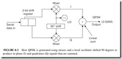
The simplest form of QAM is 2-QAM, more commonly called QPSK or quadrature phase shift keying. It is produced by the circuit shown in Figure 8.5. It takes the serial bitstream and passes it through a 2-bit shift register produc- ing two parallel bitstreams at half the rate. One is called the in-phase (I) bit- stream and the other the quadrature (Q) bitstream. The I and Q signals are each applied to a mixer along with a local oscillator (LO) signal. The mixer output becomes part of the RF carrier. Note that the LO signal is applied directly to one mixer, but is shifted by 90 degrees and applied to the other mixer. The term “quadrature” means shifted by 90 degrees. The two mixer outputs are AM
signals but at different phases. But when they are added together, the QPSK signal is generated. With this arrangement, you can transmit data at twice the rate of BPSK in the same bandwidth.
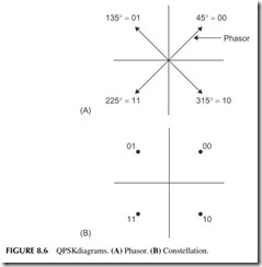
Figure 8.6 shows how we illustrate this with what we call the phasor and constellation diagrams. Figure 8.6A shows the amplitude and phase of each possible combination of 2 bits. The length of the arrow called a phasor is the amplitude, and its direction or angle is the phase. If the receiver gets a signal
that is at a phase angle of 135 degrees, it means that the 2-bit combination 01 is being transmitted. The constellation diagram in Figure 8.6B is usually shown without the arrows or phasors.
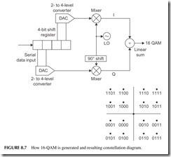
This technique can be modified to produce 16-QAM, which transmits 4 bits per time interval or symbol causing the data rate to quadruple in the same bandwidth. The circuit for producing 16-QAM is shown in Figure 8.7. The 4-bit shift register produces two groups of I and Q bits. These are converted into four levels by a two- to four-level converter that works like a digital-to-analog converter (DAC). The resulting constellation diagram for 16-QAM is shown in Figure 8.6 as well. Other common versions are 64-QAM and 256-QAM, which transmit 6 and 8 bits per symbol, respectively, in the same bandwidth.
QPSK and QAM modulation methods are common in cable TV for digital TV as well as high-speed Internet service. They are also used with satellites and any broadband wireless application. All modern cell phones and most other digital wireless schemes use this type of modulation because of its spectral efficiency.
Orthogonal Frequency Division Multiplexing
Orthogonal frequency division multiplexing (OFDM) is a broadband modula- tion method like spread spectrum/CDMA. It takes a high-speed serial binary
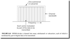
signal and spreads it over a wide bandwidth. The serial data is passed through a circuit that maps out the constellation diagram for the modulation to be used. It then divides it into many slower-speed serial bitstreams. Each bitstream modu- lates a carrier on one of many adjacent carriers in the available bandwidth. This technique effectively divides a wide bandwidth into many narrower subchan- nels or subcarriers as shown in Figure 8.8. Sometimes dozens of channels are used, and in other cases hundreds or even thousands of carriers are used. The carrier frequencies are selected so they are orthogonal and as a result they will not interfere with one another even though they are directly adjacent. All the modulated channels are then added together and the combination transmitted in the available bandwidth. The type of modulation varies with the application but it is usually BPSK, QPSK, 16-QAM, or 64-QAM.
The basic technique is shown in Figure 8.9. The only practical way to cre- ate an OFDM signal is by using DSP. The DSP executes an algorithm called the inverse fast Fourier transform (IFFT) that creates the multiple adjacent modulated carriers. The DSP data is applied to DACs to create I and Q signals that are sent to mixers for creation of the final signal. At the receiver, the data is recovered by another DSP executing the FFT. The output is the original fast serial data.
OFDM seems impossibly complex while seemingly hogging spectrum space. Yet, it can transmit higher speeds in smaller bandwidths than most other types of digital modulation. It is very spectrally efficient. Furthermore, it is more resistant to multipath interference that can cause microwave links to lose data due to a reflected signal interfering with another or a direct signal causing cancellation and fading. Most of the new wireless technologies today use OFDM, including the forthcoming LTE cellular systems. Some examples of other OFDM uses include wireless local area networks (WLAN), wireless broadband (WiMAX), digital subscriber line (DSL) Internet access, digital TV, and AC power-line networking.
Multiple Input Multiple Output
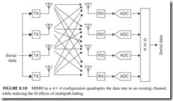
Another technique for boosting speed within a given bandwidth is multiple input multiple output (MIMO). Also known as spatial multiplexing, it is the use of multiple transmitters transmitting to multiple receivers, each sending different bitstreams on the same channel. The high-speed serial data is divided into two, three, four, or even more bitstreams, and each is used to modulate a different transmitter but operating on the same frequency. The signals from each transmitter reach the antennas of each receiver along with any reflected signals. See Figure 8.10, which shows four transmitters (Tx) and four receivers (Rx) or 4 X 4 MIMO. What allows the receivers to sort out each bitstream is the fact that each signal travels a different path, and will have different charac- teristics or spatial signature that can be sorted out by DSP in the receiver.
There are several things that make MIMO practical. First, MIMO is used at very high frequencies, especially microwave (>1 GHz). This means that anten- nas are short and inter-antenna space may be one wavelength or more, which is required for MIMO to work. The distance between the antennas ensures dif- ferent spatial paths with different characteristics that let the receivers recover each bitstream. Second, thanks to semiconductor technology, it is possible to make the multiple transmitters and receivers very inexpensively, typically all on a single silicon chip.
MIMOhas several benefits. First, it allows a higher data rate in the same channel bandwidth. Using a 4 X 4 MIMO, for example, would boost speed by a factor of 4. Configurations of MIMO can be any combination of trans- mitters and receivers. The 2 X 2 mode is popular but 4 X 4 is also used. Second, MIMO provides a more reliable link. It actually takes advantage of the multipath problems that usually plague microwave wireless and makes it
better. Finally, MIMO is usually combined with OFDM, which provides the ultimate data-rate boost, reliability, and spatial efficiency. MIMO is already used in wireless local area networks (WLAN) like Wi-Fi and in broadband wireless systems using WiMAX. Both of these technologies will be covered in the next chapter. MIMO will also be used with LTE, the next cell phone system. No, handsets probably will not have multiple antennas but the base stations will.
Spectral Efficiency
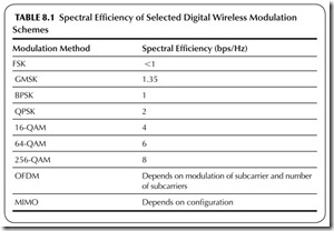
Spectral efficiency refers to how much data you can transmit in a given band- width. It is usually measured in bits per second per hertz (bps/Hz). ASK/OOK and FSK have efficiencies of <1. Special forms of FSK, such as Gaussian minimum shift keying (GMSK) used with GSM cell phones, are a bit better. BPSK has a spectral efficiency of 1. Table 8.1 gives the efficiencies of most of the popular digital wireless modulation schemes.
One last thing: the type of modulation is not the only thing that affects spectral efficiency. The level of noise in a channel also determines the number of bit errors that occur in transmission. The higher levels of QAM have more errors, so this limits their efficiency to some extent. Plain FSK, BPSK, and QPSK are very resistant to noise, so are more suitable in applications where noise is a problem. Noise and bit rates have to be traded off for good reliable transmission. And by the way, the spectral efficiency issue applies to wired as well as wireless communications channels.
ACCESS METHODS AND DUPLEXING
Access methods are wireless techniques that allow multiple users to share a given part of the frequency spectrum. Access methods are also called multiplex- ing. Multiplexing means allowing two or more signals to be transmitted concur- rently over the same communications medium such as a cable or within a given frequency band. Access methods allow many subscribers to share precious spec- trum space. And they provide the means to implement full-duplex simultaneous transmit/receive that most phone users expect. There are four types: frequency division multiple access (FDMA), time division multiple access (TDMA), code division multiple access (CDMA), and orthogonal frequency division multi- plex access (OFDMA). For full-duplex operation, there are two methods— frequency-division duplexing (FDD) and time-division duplexing (TDD).
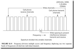
FDMA—A given bandwidth is divided into many narrower channels as shown in Figure 8.11 . A given radio will cover all of the bands but has the ability to select a specific operating frequency. GSM divides the band into 200-kHz channels. cdma2000 uses 1.25-MHz channels and WCDMA uses 5-MHz channels. The newer OFDM uses 5-, 10-, 15-, or 20-MHz channels. FDD—Simultaneous transmit and receive is accomplished by using two different bands where half are used for transmit and the other half for receive. The transmitter and receiver operate at the same time but on differ- ent frequencies so they do not interfere with one another (see Figure 8.11). TDMA—With this method, a single-frequency channel is used, but the sig- nal is divided into fixed-duration time slots into which digitized segments of voice or data are transmitted. In digital voice transmission, the analog voice
signal is periodically sampled and digitized into a stream of binary num- bers. These binary values are then compressed into a smaller number of bits by a vocoder circuit. The resulting bits are then transmitted to the receiver. With TDMA, binary values from two or more voice sources can be inter- leaved and sequenced, and then sent over the single channel. For example, in GSM systems, there are eight time slots, as shown in Figure 8.12 . The data is transmitted at a 270-kbps rate in a 200-kHz wide channel. Each time slot contains 1 byte of the voice data for one phone call. The frame of eight signals is then repeated.
TDD—Time-division duplexing facilitates concurrent send and receive by assigning transmitted signals in one time slot and received signals in another time slot. They share the same frequency channel. Because all this is happening at a high rate of speed, you cannot determine that transmit and receive are not simultaneous, although in reality they are not.
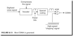
CDMA—This method uses spread-spectrum technology. It takes the digitized voice and further processes it to give it special coding, and then spreads it over a wide bandwidth. In cdma2000 phones, the channel bandwidth is 1.25 MHz wide, and all cell phone signals are coded and spread over this bandwidth. The process goes like this: the analog voice signal produced by the micro- phone is digitized in an ADC, and then compressed by a special digital cir- cuit called a vocoder or voice coder. This reduces the total number of bits and the speed of the digital signal. This vocoded signal is then mixed with a high-speed serial code signal, making it unique so that the receiver will recog- nize it. This is done with an XOR gate as shown in Figure 8.13. The higher- frequency signal, at 1.23 Mbps, is called the chipping data. The resulting sig- nal fills the 1.25-MHz channel. In WCDMA systems, the process is the same, but the chipping signal is 3.84 Mbps and the channel width is 5 MHz.
Many cell phone calls are then transmitted on the same channel. They actu- ally all mix together, but because they occur randomly with one another, they do not interfere with one another. Typically, up to about 64 users can share the same bandwidth. One signal simply appears as a low-level noise to another. The desired signal is picked up at the receiver by recognizing the unique code given to the transmitted signal. The two most common types of spread spectrum are direct
sequence and frequency hopping. Direct-sequence spread spectrum (DSSS) is used in cell phones as illustrated in Figure 8.13. Frequency hopping is used in Bluetooth wireless systems (see Chapter 9). Most duplexing is by FDD, but some of the newer versions of WCDMA also use TDD.
OFDMA
Access with OFDM is done by just assigning one or more of the subchannels to each phone call. With each subchannel 15 kHz wide, each is capable of car- rying a compressed (vocoded) voice signal so that many calls can be handled. In practice, more than one channel may be used, depending on the specific frequency assignments, bandwidths, and other features of the LTE system being used.
A LOOK INSIDE A 3G CELL PHONE
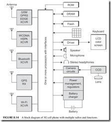
Figure 8.14 shows the insides of a modern 3G cell phone. This one uses the WCDMA/HSPA 3G technology, but is also backward compatible with GSM/ EDGE if an area does not have 3G yet. There is a separate radio transceiver (XCVR) for each. All of the baseband functions like modulation and demodu- lation and handset management are handled by one or more processors. One processor may be DSP. This handset also has a Bluetooth radio for the head- set (not shown) and a Wi-Fi transceiver for Internet access via a wireless LAN access point or hot spot. These technologies will be covered in the next chapter. A GPS radio provides navigation as well as fulfills the E911 require- ment. Note that all radios have separate antennas. A camera in included. The CCD is the charge-coupled device that converts the light and color variations in the scene into electrical signals. The stereo headphones are for the MP3 music player.
THE LATEST CELL PHONE TECHNOLOGY
The cell phone industry is one of the fastest changing in electronics. New products come out almost daily. And new features and capabilities are invented regularly to keep the technology fresh and the sales continuous. Here is a snap- shot in time of the latest cell phone developments.
Smartphones
A smartphone is a basic cell phone but with advanced features that expand its use. The basic cell phone does phone calls or at most handles text messaging as well. But a smartphone has multiple functions. Some examples of smart- phones are the BlackBerry models from Research in Motion (RIM), Apple’s iPhone, some Nokia models, the Palm Pre, and various models from Samsung,
LG, and Motorola. They are too numerous to mention and they go out of date monthly or yearly.
High-speed data capability. Most smartphones use 3G technology, so they can deliver almost as fast a data rate as your home Internet connections, usually 1 to 2 Mbps or better.
Internet access. A built-in browser lets you access the Internet just as you would from your home laptop. The main limitation is the small screen size, which prevents you from doing as much as you would like, but you can still do it.
Email. Email is one of the key features of a smartphone. It lets you stay in touch without a PC or laptop.
Messaging. It goes without saying that text messaging is a main data feature.
Digital camera. Most smartphones have an excellent high-resolution cam- era built in. It is not as great as a stand-alone digital camera, but it does have 1 to 3 megapixels of resolution.
Camcorder. Some of the digital cameras have video capability as well. The main limitation is the amount of memory available to store videos.
MP3/iPod. A music player is a standard feature of many smart phones. The key here is to have sufficient flash memory to store the songs you want.
Wireless local area network (WLAN) access. You will learn more about this in the next chapter, but a smartphone has a built-in separate transceiver to connect to a Wi-Fi hot spot or other access point in airports, hotels, coffee shops, and other locations just like a laptop. You can access the Internet or email as an alternative to doing it through the cellular network.
Bluetooth. Bluetooth is another short-range wireless technology covered in Chapter 9. It is used in smartphones for wireless headsets. A headset con- tains a headphone and a microphone that fits in the ear. It talks to the cell phone wirelessly via a Bluetooth link.
GPS. The global positioning system is the worldwide satellite navigation system. Many phones have a built-in GPS receiver so that you can find your way. Some even offer full navigation software and display as in those personal navigation devices (PNDs) like those from Garmin and Tom Tom.
Femtocells
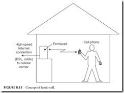
One of the most frustrating problems cell phone users have is poor cover- age at home. Many homes are not located near cell sites or have poor indoor performance. This is maddening to many, especially those who want to give up their regular wired home phone and go only wireless. One solution to this problem is the femtocell. This is a small base station designed to be installed at home. The concept is illustrated in Figure 8.15. It can usually accommo- date calls from up to four cell phones. The femtocell connects back to the car- rier via your high-speed Internet connection, a DSL line, or a cable TV link.
It provides great in-home coverage and has the added benefit that it offloads to the cell site and the carrier, providing more capacity to others.
Femtocells are just now becoming available but will soon be rolled out nation- ally. It is expected that the new LTE systems will make extensive use of femto cells.
Mobile TV
Video is now available on some phones. This video comes to you over the cell phone network, so it uses the high-speed data connection. Video is very data intensive, so it really loads down the network, limits subscriber capacity, and slows speed in some cases and raises your monthly bill. Yet, you can get vari- ous TV programs plus news, weather, sports, and comedy this way.
It has been decided that the best way to offer TV on a cell phone is to broad- cast it directly to a small receiver in the cell phone. This keeps the video data over- load off the cellular network and provides a better picture and more programming choices. This over the air (OTA) cell phone video is now available in many U.S. cities with more to come. A company and service called MediaFLO is transmitting TV to those who subscribe. Up to 15 or 20 channels provide a mix of programming. Some TV is also available in Europe using an OFDM system called Digital Video Broadcast-Handset (DVB-H). Variations are also available in Japan and Korea.
It is expected that some time in the near future, the U.S. digital TV system called the Advanced Television Systems Committee (ATSC) standard will be available in a mobile version that can be received via free OTA if the phone has a receiver built in. In all systems, the video is highly compressed using a standard referred to as H.264 and reformatted for a 360 X 240 pixel screen.
Location Technology
Location technology refers to systems and circuits that are designed to pinpoint the location of a cell phone in use. This can be done now to a certain extent, as a carrier can always determine which cell site a phone is currently using. That only locates the phone within an area of a few miles. The FCC has mandated that all cell phones can be located within 50 to 100 feet in case of an emergency. This is part of the E911 system for all cell phones. E911 means that your cell phone company has a system that will send your physical location to emergency services if you call 911 from your cell phone. Some systems use GPS, but others have another type of location technology. The whole thing is transparent to a user, and most users actually do not know that their phone has this capability.
The location capability has many concerned for privacy reasons. But if you don’t want to be located, turn off your phone. Otherwise, learn to live with it, as it many save your life one day. Location technology is also supposed to lead to services that are based on location, such as advertisements for restaurants and other businesses near you.
When GPS is used, the GPS receiver computes your coordinates from the satellite signals and sends them to the carrier for use if called for. In another system, your location is determined by actually triangulating your phone with three nearby cell sites. No additional electronics are needed inside the phone, but special antennas, receivers, and other gear are needed at the cell sites. Both systems can usually pinpoint you within 50 feet or so depending on terrain and environment.
Project 8.1
Examine a Base Station
Go look at a cell site. The wireless phone company won’t let you inside, but you can drive close to many and examine what you can see. Especially note the antenna arrangement at the top of the tower. Most have a triangular arrangement of three antenna arrays that divide the coverage into three 120-degree wide areas. You will see multiple coax cables going up the tower to carry the received and transmit- ted signals. Check for a dish that connects the site to the main switching station.
Project 8.2
Check Out the Latest Handsets, Features, and Services
Go to a cell phone store and ask about what digital services are available in your area. Try to find out what the technology is, such as GPRS, EDGE, cdma2000, 1xRTT, WCDMA, HSPA, and so on. Do you have email, instant messaging, games, Internet access, transmission of color digital photos, or what?
Project 8.3
Get an Area Coverage Map
Call your cellular carrier and ask for a coverage map. Some carriers actually give you this, but many times you have to ask for it. It may also be on your carrier website. The map will show you the actual range and coverage of the system. If you leave the area, you may have no coverage or you may switch over to another system in a roam mode.
Project 8.4
ID the Carriers
Identify the cell carriers (ATT Wireless, Cingular, Verizon, Sprint, Alltel, MetroPCS, etc.) in your area. If they advertise locally in the newspapers or in cell phone stores, they cover your area.
Project 8.5
Relevant Websites
There are several great websites where you can get additional information on how cell phones work. Here are a couple that I like: www.howstuffworks.com and www.sss-mag.com.
