XEROGRAPHY
The successful, commercial exploitation of xerography has resulted from the integration of a number of electrostatic process steps. The creation of an electrostatic image, which allows development by charged, pigmented particles, forms the basis of the xerographic process. These particles can then be transferred to plain paper and subsequently fixed to provide a permanent copy. The generation of the electrostatic image in all xerographic copiers depends upon the phenomenon of photoconductivity, whereby a material’s electrical conductivity will increase by many orders of magnitude under the influence of light. By initially charging the photoconductor to a high, uniform surface potential, light reflected from the background areas of the original causes charge decay in the corresponding area of the image. Thus, a charge pattern remains on the surface of the photoconductor corresponding to the original document.
XEROGRAPHIC PROCESS
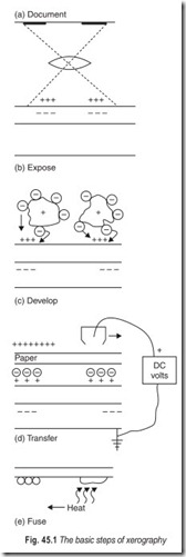
The basic steps in the xerographic process are depicted in Fig. 45.1. Charging or sensitization of the photoconductor to a uniform surface potential of 800–1000 V is usually accomplised by a corotron. Literally a thin wire, stretched between terminals parallel to the photoconductor surface, and driven at approximately 8000 V, the corotron emits a corona of ions which deposit on the photoconductor surface. The charged photoconductor must be kept in the dark to prevent discharge.
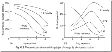
Exposure of the sensitized photoconductor to light reflected from the original to be copied generates the required electrostatic image. Voltage decay occurs via photon absorption by the photoconductor surface with the creation of an electron-hole pair. These separate under the influence of the electrostatic field, the electron neutralising a surface charge, and the hole, transported through the photoconductor neutralises the corresponding image charge at the photoconductor–substrate interface. Selenium obeys the reciprocity law in that it responds to the product of light intensity and time, regardless of their individual values. Typical light discharge and electrostatic contrast character are shown in Fig. 45.2.
Xerographic development of the latent electrostatic image renders the image pattern visible. To ensure selective development of the image, the black toner particles are charged to a polarity opposite to that of the photoconductor surface. Toner consists of finely dispersed carbon black in a thermoplastic polymer matrix. The toner particles are small to ensure that reasonable image, edge definition and resolution performance are obtained. Usually transported to the development zone via a carrier, it is the careful selection of carrier- toner pairs that ensures the correct charging and hence development characteristics.
Transfer of the developed image from the photoconductor surface to plain paper is effected by a corotron. Similar in design and process to the charge corotron, positive charge is sprayed onto the back of the paper, which itself is in contact with the developed photoconductor surface. Sufficient fields are generated to ensure that most, but not all, of the toner will transfer to the paper.
Fusing the image into the surface of the paper is accomplished by heat from a radiant fuser, or a combination of heat and pressure from a fuser roll/backup roll combination. It is this step that will dictate the rheological requirements of the thermoplastic resins used in toner manufacture. The process outlined above allows us to visualise the xerographic steps required to produce a copy via a plate photoconductor in the static mode.
EXTENSION TO A DYNAMIC COPIER
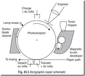
Dynamic operation of a copier places many constraints of space and geometry on the elements of process design and this in turn requires significant demands being made on the xerographic developers and photoconductors in use today. The trend towards faster, less expensive and smaller copiers will ensure that technology development will continue for sometime to come. A schematic representation of a copier is given in Fig. 45.3.
Charging remains as discussed earlier with the rotation of the photoreceptor now providing the linear motion underneath the corotron. Exposure represents more of a
challenge. With stationary platen copiers, the original document is scanned and the reflected light is transmittedvia lens, mirrors and exposure slit to the photoreceptor. Some small copiers today incorporate a moving platen and strip optics for cost considerations.
Development of the electrostatic image has been extensively studied following the trend towards, faster smaller copiers. Initial copier designs utilised a cascade development
system which poured developer over the rotating photoreceptor. Increasing process speeds demanded developer with smaller particle size (increasing surface area to mass ratio), to increase the toner carrying capacity.Cascading developer over the photoreceptor in the against mode brought some relief for further speed enhancement but the resultant development system remained bulky. The trend towards magnetic brush development systems commenced approximately 20 years ago and immediately offered the advantages of compactness and enhanced developability. The latter, resulting mainly from the fibrous nature of the brush and the density of developer at the time of photoreceptor contact, has led to almost all modern copiers using this form of development. A more recent development of this concept is the single-component magnetic brush copiers used by the Japanese manufacturers.
Apart from the optimization of currents and geometry, the process steps on transfer (and often detack) are direct analogs of the static environment.
Fusing the toner image onto the paper is one of the major contributors to power consumption within the copier and this has led to the abandonment of early, inefficient radiant oven
furnace. Centrally heated polymer-coated steel or aluminium rolls now effect fusing by a combination of heat and pressure.
Release agent fluids are often used on these rollers to prevent toner offsetting from the paper to the polymeric surface.
In the dynamic mode the photoreceptor has to be returned to a virgin condition prior to reaching the charge corotron and hence embarking on another cycle. If this is not the case, residual voltages will build up within the transport layer of the photoconductor and cyclic problems will rapidly manifest themselves and cause print to print variations. Following the transfer of image toner to a paper, a residual image (some 5.20% of the developed toner) will remain on the photoreceptor surface (Total transfer is avoided as it would increase print background levels). Removal is effected by rotating brushes in some machines, soft webbed fabric in others, but the popular choice for all small and mid-volume copiers today is the so-called doctor blade. A straight-edged polyurethane blade is angled against the photoreceptor and this scrapes the residual toner from the surface. The clean photoreceptor subsequently passes underneath an ac corotron or an erase lamp to remove all vestiges of voltage fluctuations prior to charging once again.
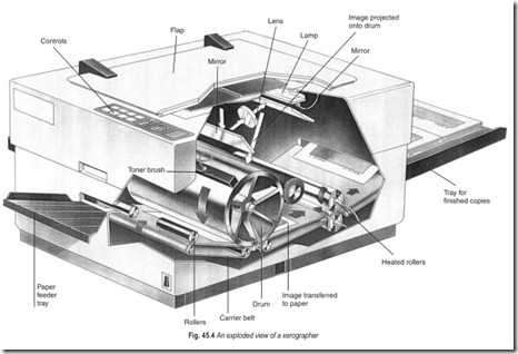
An exploded view of a xerographer is given in Fig. 45.4.
EXERCISES
Descriptive Questions
1. Explain the basic xerographic process.
2. What is the difference between a static and a dynamic copier?
Fill in the Blanks
1. The corotron emits a …………………………….. of ions which deposit on the photoconductor surface.
2. The charged photoconductor must be kept in the ……………………… to prevent discharge.
3. Selenium obeys the…………………………law.
4. It is the careful selection of…………………………pairs that ensures the correct charging and hence development characteristics.
5. Fusing the toner image onto the paper is one of the major contributors to………………………….
6. Centrally heated polymer-coated steel or aluminium rolls now effect fusing by a combination of …………………………
ANSWERS
Fill in the Blanks
|
1. corona |
2. dark |
3. reciprocity |
|
4. carrier-toner |
5. power consumption |
6. heat and pressure |


