Selecting and maintaining explosionproof motors
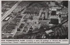
RELIABLE operation of the thousands of motors supporting research and development work at the huge Hoff mann-La Roche Inc. plant in Nutley,N.J. is the result of careful selection, effective circuit design, and a compre hensive maintenance program.
Throughout this 120-acre, 90-building complex are numerous hazardous areas, most of which are designated Class I, Division 1, Group D locations. Although some areas meet the require ments for a Class I, Division 2 classifi cation, company management has chosen to treat them as Class I, Divi sion 1 areas to simplify the specifica tion of electrical systems and equip ment. (Also, a Division 2 location might later be changed to a Division 1 location, and upgrading of equipment would then be necessary.)
Safety must thus be the foremost design consideration. Motor circuits and equipment must meet all appli cable NE Code rules, particularly Arti cle 500 (Hazardous Locations), Article 501 (Class I Locations), and Article 430 (Motors, Motor Circuits, and Con trollers). In selecting and buying elec trical equipment and components, fre quent reference to the UL Hazardous Location Equipment Directory (Red Book) supplements use of manufac turers’ literature and a common ap proach backed by years of experience.
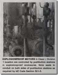
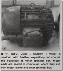
Motors for classified areas are selected to meet load and field oper ating conditions, usually with a TEFC explosionproof, Class I, Division 1 enclosure, dual-rated for either Group CorD, although some motors rated for Class II, Division 1, Groups E and F are in use.
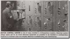
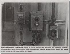
In many of the hazardous areas,motors and processes are controlled automatically from pressurized control rooms. Motor disconnects, controllers, and most other control devices are located in these rooms and thus are not required to be of special design. Posi tive pressure is maintained by hugeblowers; if the pressure drops below a predetermined level, a differential pressure switch sounds an alarm. In these installations, only the motor and an emergency STOP button are installed within the hazardous area. They are, of course, provided with proper explosion proof enclosures.
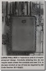
Controls or other devices required to be installed in hazardous areas are usually provided with a special enclo sure designed to be placed under posi tive pressure as described in NE Code Section 500-1.
Preventive maintenance
Preventive maintenance of explo sionproof motors is part of a planned program of regular inspections. Be cause of the thousands of explosioQ proof motors installed, only those in critical applications or with a ques tionable history are included in a regular motor maintenance program. However, most explosionproof motors are checked during a regularly sched uled equipment inspection under an overall preventive maintenance pro gram.
All important or critical equipment
or systems are scheduled for periodic inspection by lubricators, mechanics, electricians, and others. During these inspections, the explosionproof motor and other electrical equipment on the machine or system receive a thorough visual inspection.
During scheduled electrical preven
tive maintenance inspections, the elec trician looks for excessive dirt, noise, heat or corrosion. More extensive checks are made during periods when portions of the plant are shut down for maintenance procedures. These checks may include vibration analysis and insulation-resistance tests. All test procedures, instructions and special notes are provided for each major equipment or system. Records of all findings-voltage and current readings, condition of enclosures, belts,clutches, drives, etc.-are recorded for future reference .
Electrical troubleshooting
When an electrical problem in a hazardous area is suspected, either during night-shift inspection or during a regular working day, special proce dures must be followed.
First, an experienced plant electri cian, trained to work in hazardous areas, is called to observe the problem and make an analysis and judgment based on a visual inspection, if possible. For example, if a motor and/or load appear to be operating improperly, the electrician first visually inspects the components, watching for damaged, discolored or loose parts; listens for any unusual noises; feels the equip ment for overheated components; and determines if any unusual odors exist. The equipment operators and area production supervisors often supply clues that help to solve equipment problems.
If further investigation is required,electrical tests can be made easily if control equipment and disconn ects are remotely located in a nonhazardous area. If electrical tests must be made within the hazardous area, a special “safety shutdown clearance” must be obtained. This clearance is required even if tests are to be made on de energized equipment.
The shutdown clearance procedure is carried out by the safety departm ent, area chemists, and specialized techni cians. The technicians check temper a tures, gas or vapor content of the area and use special instruments, such as an explosimeter, to make sure the area is safe for electrical troubleshooting.
When the safety clearance is given , the usual troubleshooting procedures are followed. This may include discon necting the motor from the load to isolate the problem; checking control circui ts devices (overload relays, float, limit, pressure switches, etc.); and checking voltage at motor terminals.
The troubleshooting technique in cludes two special steps:
1. The saf est possible trouble shooting tests are selected and used. For example, continuity tests of motor windings would be used prior to a voltage check at the windings.
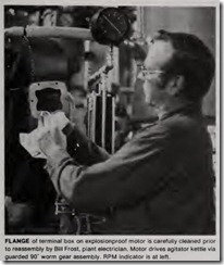
2. Equipment enclosures are han dled with great care during disas sembly or reassembly. Mating surfaces are carefully checked for gouges or scratches, since for proper and safe operation, the machined surfaces must be maintained in perfect condition. In most instances, only the terminal box is opened. If further disassembly of the motor is required, a certified service firm is called in.
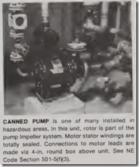
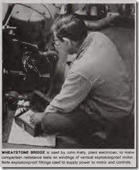
Accompanying photos provide additional maintenance and trouble shooting details.
