Reducing motor losses
Energy can be conserved and power bills significantly reduced if motor losses are minimized. These articles will examine motor losses and cost-effective methods of reducing them.
Part 1-Motor losses and efficiency
REDUCING losses in electric motors presents a tremendous potential for saving electrical energy. Much effort, media attention, and federal and state regulations have been de voted to lighting levels and energy efficient lighting, yet lighting accounts for only about 20% of the total electri cal power consumption in the United States. Electric heating and miscella neous applications account for about
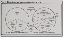
another 16%. By far the largest use of electr ic power is to drive motors-64%, or nearly two-thi rds of the total elec tric power consu mption, according to a 1976 report of the Federal Energy Ad ministration (now the U.S. Dept. of Energy). Of this motor use, about 14% of the power con sumed is for residen tial and other sm all motors, mostly single-phase, fractional-horsepower . The remaining 86% is for industrial, commercial and electric utility motors , almost all 3-phase, integral-horsepow er (Fig. 1). Motors consume electric power equivalent to about 6 million barrels of oil per day-33% more than automobiles. Thus, any reduction in motor power consumption can be extremely valuable to the economy of the nation as well as saving the user substantial costs of motor operation.
Several approaches to minimizing motor losses may be used. Proper matching of the motor to the load which does not always mean loading the motor to its full rating-can result in minimizing losses.* High-efficiency motors are now available having lower losses for a given load than standard motors, often saving enough in power to repay their cost premium in a very short time. A new invention by Frank Nola of the National Aeronautics and Space Administration (NASA) is now commercially available. Called a “pow er factor controller,” it shows great promise of lowering motor losses. Another device, the “alternating-cur rent synthesizer” (ACS), can also pro duce great economies where loads are not constant. The ACS provides vari able frequency and voltage to a motor, adjusting the motor speed to match the required output. New technology is reducing the initial cost of the A CS variable-speed drive to a point where it is often a desirable choice.
We will examine the nature and measurement of motor losses and then evaluat e the advantages, disadvan tages, and economics of high-efficiency motors, the power-factor controller, and the A CS variable-speed drive as means for reducing these losses.
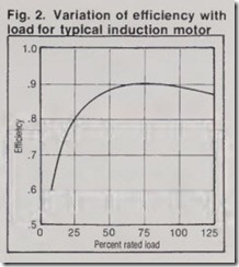
The nature of losses The total power consumed by a motor consists of the power used for driving the load and power lost within the motor. The ideal motor would have power input exactly equal to the work done or pow er output, and be 100% efficient. Real mot<‘ rs waste some pow er. The losses for a typically loaded motor are about 10% of total power input for large integral-horsepower motors, 10% -15% for smaller integral horsepower motors, and often more for fractional-hors epow er motors. A light ly loaded motor will have higher losses as a percentage of input power than the same motor loaded to nearl y its full rating, since the fixed losses are con stant regardless of load. Since motors are rarely loaded to 100% of their rating, they are designed to be reasona bly efficient when loaded from about 60% to 100% , with maximum efficiency in the 75%-80% range in most cases (Fig. 2). Efficiency is very low at light loads, and since an unloaded motor does no work but consumes some pow er, efficiency drops to zero at no load.
Power losses in a motor are that portion of the input power t hat becomes heat rather than driving the load. These losses can be divided into two basic categories-fixed losses and variable losses. Fixed losses are assumed to be constant at all condi tions of motor loading from no load to full rated load. This is not exactl y tru e, but it is nearly so, and little significant error is created by this approximation . Fixed losses include magnetic core losses (hysteresis and eddy current) and mechanical friction losses (bearing friction, brush friction, and air friction or windage). Variable losses are those that vary with the load on the motor and thus with the motor current. These losses increase as the load on the motor, and therefore the current drawn by the motor, increase . They are primarily the power lost in the resi st ance of the motor windings and are often called copper losses, or FR losses.
Variable losses also include stray load losses, such as minor variations in fixed losses with load and speed and other small miscellaneous losses. Vari able losses are approximately propor tional to the square of the motor load current.
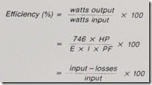
motor divided by the el ectrical input to the motor, usuall y expressed as a per centage. Power or work ou tput is input less losses.
Winding losses
Motor efficiency is the output of the speed. Some motors are designed to run at synchronous speed, and these have a wound secondary con nected through slip rings and terminals to an external de power source. The greatest number of motors, by far, are squirrel cage induction type. In this discussion of losses and their elimination, we will con sider mainly this type of motor.
Winding losses are often called “cop per losses,” but today this is not strictly correct. Many motors, especially fractional-horsepower and smaller in tegral-horsepower units, have stator windings of aluminum wire. Most motors today have armatures with the conductors, end rings, and fan blades cast of aluminum as a single unit. A more accurate term would be J2R losses, indicating power converted to heat by the resistance of the copper or aluminum conductors. The total J2R Voltage applied to a motor drives
current through th e motor windi ngs. In the typical 3-phase inducti on motor, voltage is applied directly to th e stator, or prima ry win ding, and induced cur rent flows in the rotor, or secondary winding. The seconda ry wi nding of a squirrel-cage motor consists of bare conductor s or bars, solidly con nected together by a condu cting ri ng at each end, producing a secondary winding that is part of th e rotating armature. The squirrel -cage second ary h as no external connections.
Wound -rotor induction motors have insulat ed coils in th e secon dary, with connection s t hrough sl ip rin gs to brush es and extern al term in als. A variable resistance or, more rarely, a separat e voltage source, is connected to these secondary winding termi nals to vary th e slip and therefore th e motor losses are the sum of the primary (or stator) J2R losses and the secondary (or rotor) J2R los:ses (includi ng any brush and contact losses for wound-rotor motors).
The actual J2R losses in the windings will depend not only on the current, but also on the winding resistance under operating conditions. The actual, effec tive resistance of a winding will vary with temperature, load, excitation, ac skin effect, magnetic influences, un even sharing of current among conduc tors, and similar factors. Even for one specific set of conditions it is extremely difficult to determine the true values of winding resistance. Standard loss-mea surement practice, therefore, uses as the resistance value the de resistance at the steady winding temperature attained where the motor is run at full load in a 25•c ambient. Resistance calculations are corrected to this tempera ture. Errors introduced by this as sumption are compensated for, along with other small losses, by considering them as stray load losses.
Core losses
An induction motor operates by gen erating a rotating magnetic field, which causes the armature to rotate. To make the motor efficient and rea sonable in size, the magnetic fields are concentrated and directed by high quality magnetic steel in both the field (stator ) and armature (rotor), with a minimal air gap between them. When the molecules in the steel are magne tized first in one direction and then in the other by the applied alternating current , there are energy losses in the steel. These show up as heat and are known as hysteresis losses. These losses increase with increasing mag netic flux density (higher current) and also with increasing frequency of the applied voltage.
The alternating magnetic field also induces small voltages in the steel core, which causes random currents to circu late within the steel. These are known as eddy currents, and acting on the resi stance of th e steel they also produce power loss that appears as heat.
Eddy-current losses are minimized by making the steel cores of many thin laminations of steel, insulated from each other, in both the field and arma ture. Eddy-current losses vary with flux density and f requency of flux vari ation, as do the hysteresi s losses, and th ese two are usually combined under th e term core losses.
Core losses vary with the load curren t on th e motor, speed changes, and other conditions of operation. It is very difficult to measure them under dy namic conditions. Theref ore, the ac cepted meth od for determining core losses measures them under a standard set of conditions and assumes they are constant over the load range of th e motor . Inaccu racies resulting from this assumptio n are accounted for under stray load losses.
Mechanical losses
Friction and windage losses are the mechanical energy consumed by the motor in overcoming bearing friction, the friction of brush es against commu tator or slip rings (if any), and the friction of the moving parts, especially the cooling-fan blades, through the surrounding air. Th is lost energy is converted to heat, as are all other losses. Mechanical losses are assumed to be constant from no load to full load, which is a reasonable approximation but not absolutely accurate. As with core losses, any inaccuracies are accounted for under stray load losses.
There is no simple method of calculating mechanical losses. They must be determined by testing according to an accepted procedure. For those ac motors having brushes, testing is done with the brushes in place, on the slip rings, so that the total friction, includ ing brush friction, is measured. For de motors, brush friction against a com mutator varies considerably with brush and commutator surface condi tion, so testing is done with the brush es lifted off the commutator. A stan dard wattage, depending on brush type and size, is added to the measured value to account for brush losses in de motors.
Stray load losses
We have seen that several types of losses are assumed to be constant over the no-load to full-load range of the motor, although we know that they actually vary slightly with load. In addition, there are some losses that we cannot calculate. As a result of flux variation with load, skin effect, and conductor geometry, the current will be divided among the conductors some what unequally and will be less than perfectly uniform over the conductor cross-sections. Also, as current in creases, conductor temperature will increase, causing an increase in con ductor resistance and therefore in con ductor losses. As magnetic flux in creases with load current, there will be some increase in magnetic core losses. All these minor losses, from both known and unknown sources, are lumped together as stray load losses, which tend to increase with load. They are determined by standard test proce dures and calculations , and it is in the calculation of stray load losses that substantial variations in calculated efficiency can result.
Measuring efficiency and loss
It would seem that measuring effi ciency should be a simple matter. Just load the motor, measure the mechani cal power output, and measure the electrical input with a wattmeter. If we know input and output, efficiency can be calculated easily from the previously given formula. Unfortunately, things are not that simple and straightfor ward. A 1976 report to the Federal Energy Administration by the consult ing firm of Arthur D. Little, Inc. stated,Reliable and consistent data on motor efficiency is not now available to motor appliers. Data published by manufactur ers appears to range from very conserva tive to cavalier.
In the absence of clear standards for efficiency testing, comparing data from different manufacturers was not a reli able means of choosing among motors. In fact, it penalized the conservative manufacturers and favored the overly optimistic manufacturers.
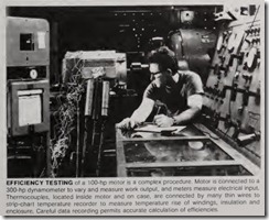
This situation has been improved considerably ith the publication of IEEE Standard 112-1978 (revised from IEEE Standard 112A-1964) and with its adoption as an ANSI Standard by the American National Standards In stitute. This document, entitled IEEE Standard Test Procedure for Poly phase Induction Motors and Genera tors, gives detailed procedures for mea surement of motor efficiency (and oth er motor testing) as developed from theoretical and experimental informa tion by the Rotating Machinery Committee of the IEEE Power Engineering Society. There are a number of other test standards in use throughout the world, but these generally are based on no-load tests and designated assump tions and calculations. Testing is faster and less costly than IEEE-112, but results tend to be overly optimistic estimates of efficiency (Table 1). The IEEE-112 Method B is difficult, and expensive, but it is the most accurate and thorough. Efficiencies are realistic, and savings will not be overstated. Note that on the same motors the three international standards gave apparent efficiencies from 2.0% to 4.7% higher than IEEE Method B. If efficiency is 80%, losses are 20%, and a 4% high efficiency measurement represents a 20% understatement of losses.
The IEEE standard lists five methods for determining efficiency. Method A uses an adjustable mechanical brake to load the motor to the desired torque. Method B loads the machine with a dynamometer to measure mechanical power output. Method C uses two duplicate motors, coupled together and connected to two sources of electrical power, one source having adjustable voltage and frequency to produce the desired loading . Methods E and F are known as “segregated-loss” methods and depend on measurement and calcu lation (Method E) or calculations based on the equivalent circuit of the motor (Method F). There is no Method D.
Method B is generally accepted to be the most accurate for motors in the range from 1 hp to 125 hp. With ade quately rated test equipment, it may be used for even larger motors. It is based on dynamometer measurements with accuracy improved by segregated-loss determination and stray load loss mea surement. Segregated-loss determina tion requires separate measurement and calculation of each type of loss that is, friction and windage losses, core losses, stator f2R losses, rotor f2R losses, and stray load losses. Some of the greatest variation among motors can occur in the stray load losses, and the standard indicates ways to mini mize errors and excessive optimism in determining these losses. The test pro cedures are clearly defined, and testing is done at full operating temperature or corrections are made for tempera ture differences. Required accuracy of instrumentation is detailed. Proce dures are given to minimize or elimi nate errors.
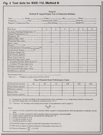
The test data and report form used for Method B is shown in Fig. 3. When test data is obtained in accordance with the methods called for in the standard, when the dynamometer is rated at not more than three times the motor horsepower (to minimize dyna mometer error), when instrumentation is of the required accuracy, and when the proper temperature and other cor rections are made, results should be accurate. In late 1977 and early 1978, to determine the reliability of efficien cy testing as then being done by motor manufacturers, the National Electrical Manufacturers Association (NEMA) conducted a “round robin” test. Three motors, one each of 5 hp, 25 hp, and 100 hp, were sent to nine different motor manufacturers, who were requested to test for efficiency at various loads, using their version of Method B of IEEE-112. The results were shocking. Variations of several percent in effi ciency were reported. This was equiva lent to typical ranges.of over ± 15% on losses for the 5-hp and 25-hp motors, and ± 20% to over 40% on the 100-hp motor, where total losses were smaller. The nine manufacturers were then requested to use the same test data, but to segregate losses, using “statisti cal smoothing” of the stray load losses. The results were distinctly improved, with the range of loss values reduced to about ±10 % for the 5-hp motor, 12% for the 25-hp motor, and 15% for the 100-hp motor .
In late 1978, the three motors were again submitted to the nine manufac turers for retesting, with the input output test method specified for use by all testers. The results were reported before and after segregated loss calcu lations. Even before segregating losses the results were noticeably better, with the range of losses about ± 13% for the 5-hp and 25-hp motors, ± 20% for the 100-hp motor. After segregating losses and smoothing stray load losses, the range was an acceptable ± 6% on the 5-hp motor, ±8% on the 25-hp motor, and ± 12% on the 100-hp motor.
This experiment resulted in the adoption by NEMA of a new standard, NEMA STD MG1-12.53, Paragraph (a) and (b), Revised January 17, 1980. This standard augments IEEE-1 12, specify ing motor efficiency testing methods to improve the accuracy and reliability of results. This NEMA standard is now being accepted as an ANSI standard. It is anticipated that the next revision of IEEE-112 will also incorporate these new requirements for testing. Motor manufacturers who label their motors as NEMA designs are expected to test in accordance with this new standard, and it is highly recommended that for efficiency calculations, motor compari sons, and power-cost determinations that all data be based on IEEE-112, Method B, as modified by NEMA MG1-12.53 (a) anp (b).
Power-factor effects
![]() It must be pointed out that low pow er factor also can be a cause of high utility billing, if the utility has a pow er-fact r penalty clause. Power-factor correction capacitors can raise the power factor and eliminate or reduce these power-factor penalties.
It must be pointed out that low pow er factor also can be a cause of high utility billing, if the utility has a pow er-fact r penalty clause. Power-factor correction capacitors can raise the power factor and eliminate or reduce these power-factor penalties.
Capacitors supply the reactive power consumed by the motor, which is not read by the kilowatt-hour meter and the demand meter. Therefore, although there may be some slight reduction in distribution-wiring J2R losses as a result of the elimination of the reactive current for capacitors located at the motors (and not even this for capaci tors located at the service equipment), capacitors do not in any way reduce motor losses. Although capacitors im prove the power factor of the system feeding the motors, the power factor of the motor itself remains unchanged. The motor cannot tell whether its reac tive power requirements are supplied by the power system or by capacitors.
