Effect of motor efficiency on energy savings
By DONALD ALDWORTH, Energy-Efficient Motor Specialist, Gould Inc., Electric Motor Div.
ENERGY-EFFICIENT MOTOR S are designed to save operating expense over their useful operating lif e. Be cause these motors generally demand a premium price over alternatives, it is necessary to justify the investment by conducting a comparative analysis. Typically, an evaluation is developed from readily accessible data, because it is not economically feasible to perf orm an in-depth analysis every time a pur chase decision is made. The evaluation is based on data supplied by motor manufacturers and assumptions per taining to the operating conditions of installation.
Assuming the evaluation indicates that a high-efficiency motor is indeed the best buy, how can it be determined if the decision is correct? The proof can be obtained only by on-site testing. Is the motor performing as expected, and is it saving energy in accordance with calculations?
A review of selected installations with favorabie results lowers the risk on future purchasing decisions. On the other hand, if follow-up analysis results are unfavorable, either original assumptions were wrong or the high efficiency motor is not performi ng as expected. More than 100 in-plant watt hour-meter tests, under a variety of applications, indicate that a favorable trend has developed.
What’s the best buy?
Best-buy evaluation decisions m·e typically developed from the most readily available data. In-depth analy sis, taking into account all pote ntial variables, simply requires too much time.
The efficiency and power-fact or performance of an energy-efficie nt motor are obtained from vendor literature. The nominal efficiency value repre sents performance that is the average of a large population of motors of the same design .
For comparative analysis, the next step is to deter!l1ine the efficiency of the other motor . In most cases, the other motor is a standard-efficiency design motor, perhaps one that is already installed and operating. Deter mining the actual efficiency for this motor is a difficult task. Therefore, the performance data are often obtained from “industry average” tables. Short of submitting th e standard motor to a qualified test facility, using the aver age table is sufficient for most initial evaluations.
A rmed with performance data and prices of standard and high-efficiency motors, an evaluation of the best buy req uires estimation of operating time and energy cost. These variables are functions of the application and input obtained from the user.
The most basic evaluation requires the following minimum information:
Efficiency–a measure of how well the motor converts electrical energy input into mechanical work output (watts in + watts out).
Op erating time-the number of hours per day, week or year the motor is expected to operate.
Energy cost –the total cost of ener gy ($/kW h ) including the basic rate charge, power -factor penalti es, de mand, and f u el-adjustment cha rgfls. It is obtained by dividing the total kilo watt hours into the total u tility ch arge.
EXAMPLE
A ssume that two 40-hp motors-one a standard motor (A) with a stated efficiency of 89.5%, the other (B) with a 92.4% efficiency-are to be operated 6000 hrs/yr. The total cost of energy is
$0.05/kWh. Savings realized by the increased efficiency of motor B are given by the equation ![]()
Substituting the given data in the equation r esults in a savings of $314/yr.
This evaluation is only as accurate as the input data. The efficiency input data are derived from statistical aver ages. No two motors are created equal. Manufacturing variances give each mo tor a personality of its own. In practice, similarly rated motors will actually have efficiencies within a tolerance band centered around the average or nominal. Through various sampling tests, NEMA has determined that a deviation may be expected of ± 20% of motor losses and subsequently devel oped a standard that provides a com mon means of testing and labeling motor efficiency. NEMA MG 1-12.53 a and b establishes a common language for comparing motors made by various manufacturers. It defines the method of testing, interpretation of test re sults, and nameplate marking. Testing and labeling standards apply to new motor production.
Factors affecting motor performance
From a simplistic point of view, a motor is used to convert electrical ener gy into mechanical rotating energy (power). In the laboratory, motor designs are evaluated for their effec tiveness by the monitoring of several key parameters under ideal power-sup ply conditions. The results are com piled in published literature and marked on nameplates to be used in the selection of motors for actual job applications.
When installed on a jobsite, the motor is subjected to an environment different from the laboratory thus motor performance on the jobsite is different from its performance under laboratory conditions.
The power supply to which an alter nating current motor is connected directly affects the motor’s operating performance. Variations in voltage, frequency and load will affect motor efficiency and power factor.
Effects of voltage variation. NEMA
Standard MG1-12.43 states that alter nating-current motors shall operate successfully under running conditions at rated load with a variation in volt age (at the motor terminal leads) up to plus or minus 10% of the design value. In the interest of a more flexible design for general application, NEMA Stan dards define the voltage variation that all motors-standard or high efficien cy-must meet.
A differentiation must be made between system voltage and applied voltage. System voltage is supplied to users by an electric utility or by in plant substations through transform ers and can usually be adjusted by taps. (For example, plant system volt age = 480/240 V.) Applied voltage (motor nameplate voltage) is the volt age at the motor terminal leads, which allows for the PR or voltage drop through distribution lines in plants or buildings. (For example, the industry standard at motor terminals = 460/230 V.)
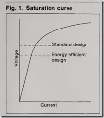
Much of the effect of voltage varia tion at the motor terminals depends on how hard the motor design is working the magnetic iron. If the motor’s design is working “light” magnetically, the volt-versus-amp relation is basical ly linear. Most energy-efficient motors are designed this way. On the other hand, if the motor’s design runs close to saturation, the relation is not linear. Current will increase in greater pro portion to an increase in voltage. (See Fig. 1.) Many standard T-frame motors are designed to operate at full load, near the saturation point.
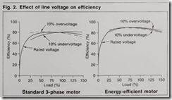
The efficiency of a motor operating at full load is not likely to change much with small voltage variations, because stator and rotor J2R losses tend to move in a direction opposite to the core loss. Thu ·<, there is little cumulative change. At other than full load, how ever, variations in voltage result in a more significant loss of efficiency, as reflected in Fig. 2. Energy-efficient motors, due to their design and con struction, are generally more tolerant to voltage variation. Notice the differ ence between the motor types, the standard motor being influenced in the normal load range and the energy efficient motor being affected only at loads above 100%.
Since magnetizing current increases with voltage, the power factor of an induction motor becomes lower at volt ages higher-than-rated. At lower volt ages, the power factors will generally show improvements.
As with efficiency, power factor will change more drastically with voltage variations with standard motors than it will with energy-efficient motors.
Reduction of motor efficiency due to high or low voltage applied to the motor terminals can be corrected in the user plant by a number of established engineering methods. The simplest action would be to adjust the tap set tings on the appropriate transformer. Most low voltage problems are caused by excessive voltage drop in the lines feeding the motor. If the loads vary considerably over the course of a typi cal dav, automatic tap-changing equip ment may be required. If the motor is at the end of a long feeder run, voltage drop may be reduced by rearranging the system. Since the cause of voltage drop is current (FR), the reactive com ponent of current draw can be reduced by correcting power factor.
Voltage unbalance. Up to now, we have assumed the application of a bal anced 3-phase voltage above or below the nameplate value. Another varia tion of particular importance to the smooth and efficient operation of an induction motor is voltage unbalance. The % phase-to-phase voltage unbal ance is best illustrated by the relation ship
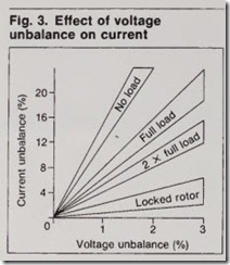
When the line voltages applied to a polyphase induction motor are not exactly the same, unbalanced currents flow in the stator windings. The effect of unbalanced voltages on motors is a “negative sequence” voltage having a rotation opposite to that of balanced voltages. Unbalanced voltage produces a corresponding negative-sequence flux causing unbalanced current in excess of those under balanced voltage condi tions. The level of full-load current unbalance will generally be on the order of six to ten times the voltage unbalance, and this increases as the load decreases. (See Fig. 3.)
The efficiency of the motor falls off dramatically as the voltage unbalance increases. For example, a 3.5% voltage unbalance will result in about a 25% increase in losses and corresponding temperature rise. Also, even a rela tively small unbalance will cause the temperature of the motor to rise rapid ly. In the phase with the highest cur rent, the percentage increase in tem perature rise will approximate two times the square of the percentage voltage unbalance. Such an unbalance can also result in electromechanical vibration, leading to bearing failures.
One common cause of unbalanced voltage conditions is an open circuit in the primary of the distribution system. Unevenly distributed single-phase loads on the same power-supply system is another cause of phase-to-phase unbalance.
Whatever the cause, it should be corrected. Excessive current will result in increased motor losses, deterioration of efficiency, and shortened motor life. Load. Most electric motors do not operate at rated horsepower, which means that the nameplate efficiency, power factor and current do not apply.
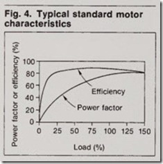
Nameplate values are generally as sumed to be at “full load” or “rated” conditions. Data sheets covering various load points are usually available from manufacturers. Fig. 4 illustrates
the effect on efficiency and power factor as the load changes for a typical motor.
Efficiency is essentially constant over a range from 50 to 125% of full load. Power factor is more severely affected by underloading. By compari son, energy-efficient motors have simi larly shaped curves but their efficien cies are generally higher for any load point. Of course, every motor design has its own unique load curves, with peak efficiency occurring at less than, or greater than, full load.
Thus, when evaluating potential en ergy savings of motors with different designs, it is best to perform the evalu ation with efficiency and power factor values corresponding to the anticipated loading of the specific motors. For example, assume a pump application requires a 40-hp, 4-pole motor. The efficiency of a standard motor is 89.3% and an energy-efficient design is 92.0% at full load. At continuous operation, the savings will be 8590 kWh per year. In reality, however, the motor is oper ated at % load, and the respective effi ciencies at this load point are 88.0% and 92.4%. The calculated annual sav ings jumps to 14,145 kWh per year.
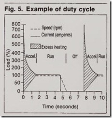
Duty cycle is another consideration of load that infers varied loads over time. Usually the duty cycle is repeti tive and can be represented by a time graph. Strip recorders displaying cur rent or watts versus time are examples of instruments used to obtain duty cycle information.
If a duty cycle requires the motor to be shut off for part of its cycle as shown in Fig. 5, then excessive temper ature rise may become a problem. Starting current will generate heat energy (losses) in proportion to the square of the current. On the other hand, a motor’s ability to dissipate heat by ventilation is proportional to the square of the speed.
Motors applied to duty-cycle loading do not experience constant load, and therefore the efficiency performance is also varying over time. The average load and therefore average efficiency can be approximated; but remember that an idling motor performs no use rul work but may be drawing 30% of its full-load kV A.
Other variables. Other environmen tal conditions affect efficiency. Al though harder to measure, they can have significant influence over motor performance. In general, these influ ences fall into the category of mainte nance. Poor maintenance will ultimate ly shorten motor life. The most-common result is premature failure be cause of excessive temperature rise. Bearings and insulation life are most vulnerable to excessive heat. Heat is energy and therefore exactly the sort of motor loss to avoid.
There are a number of common abnormalities that have an adverse effect on a motor’s performance. These include mechanical misalignment, im proper bearing lubrication, improper V-belt application, and ambient tem perature and ventilation.
Another area of concern is the effect of rebuilding/rewinding a failed motor. The process of burning out the old windings has the potential of increas ing core losses. If the burnout tempera ture is exce.ssively high, above 750°F, the magnetic properties and interlaminate insulation may be degraded and result in a motor with lower efficiency after rewind.
Case studies in motor efficiency
Voltage variation, voltage unbalance, and loading affect the efficiency per formance of all motors. These factors represent the primary external influ ence reacting with the internal design. Common designs will react in similar ways. Motors of different electrical designs, such as standard and high efficiency motors, will react in a dis similar manner to the same external stimuli.
From numerous studies, it appears that variations in external conditions will generally have a more detrimental effect on standard -efficiency designs than high-efficiency designs. The three case histories reported here are typical examples that support this trend.
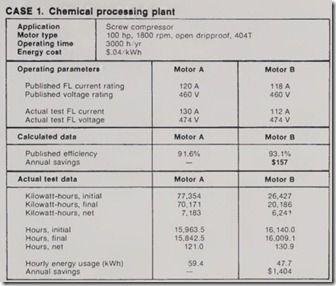
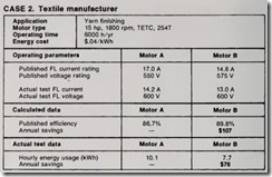
The case histories are the results of watthour-meter tests conducted on the job under operating conditions. A cumulative watthour meter with elapsed-time meter was wired into the motor circuit being tested. Test data were collected by the companies involved. The cost of energy used in these examples represents a nation wide average. The purpose of reviewing these case studies is to demonstrate the performance difference between calculated (or expected) results and actual test results. In each case, unless other wise noted, the energy-efficient motor (Motor B) substituted for the standard motor (Motor A) had the same ratings.
Comments on results
CASE 1
Voltage variation- Applied voltage is 3% higher than nominal. Because Motor B is designed at a lower point on the saturation curve than Motor A, higher voltage lowers the current draw and increases the efficiency of Motor B. Motor A reacts in an opposite direc tion.
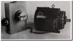
SIMPLE EQUIPMENT used to test effective ness of energy-efficient motor included an elapsed-time meter mounted on meter-sock et enclosure and a kilowatt-hour meter.
Voltage unbalance of less than 1%results in efficiency loss for both motors, but it could not be determined if there was a signific.ant difference in impact on either motor.
Load variation-Th is applicationinvolved a duty cycle that requi red the motor to run a length of time unloade d. The no-load losses of Motor A were considerably higher than those of Motor B. No-load energy con sumption is an appreciable factor in explaining the difference in average energy con sumption recorded on the watthour meters.
CASE 2
Voltage variation-Applied voltage is 4% high for Motor B and 9% high for Motor A. An analysis of the full load saturation curves for each motor reveal that both motors operate well
below the knee of the curve at theirnameplate voltage. However, at 600 v Motor A demonstrated reduced effi ciency, and Motor B showed efficiency improvement.
Voltage unba,lance-Bo th motors were subjected to the same un balance, which measured less than 1% and did not contribute signficantly to the dif ference in energy consumption.
Load variation-The driven m a chine was operated under the same load conditions for each motor, which varied from approximate ly % to 112 load.
At nameplate voltage, either motor would demonstrate similar drops in efficiency-approximate ly 1 to 1.5 points. But, under duress of the high · voltage applied, Motor A experienced a
drop of about 3 points in efficiency at 1/z load. This raised its average energy consumption throughout the load range.
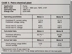
CASE 3
Voltage variat ·on- Applied voltage is 2.6% below nameplate nominal. In this application it actually helps the efficiency of both motors, because they are so lightly loaded. Low voltage tends to lower current draw, which corre spondingly decreases load losses (J2R) in the motors.
Voltage unbalance was negligible.
Load variation-Motor A was in stalled as original equipment and, because it was consistently drawing 60% of its rated amps, it was decided that the next-lower rating (5 hp) should be tested.
As it turns out, a 3-hp rating might have been a better choice for the loads run on the pump at the time. With the oversized motor, much of the power requireme nt was the reactive compo nent, which does no useful work out pu t. The energy savings were achieved primarily by sizing the motor closer to the load.
Summary
The three case histories illustrate that energy savings of actual installa tions often exceed expected savings when initial evaluation uses only nomi nal data. There were some other cases where installation of energy-efficien t motors did not achieve anticipated results. The most probabl e reason for those cases was either that the standard motor had better efficiency than assumed or the high-efficiency motor had lower. But in the majority of installed tests, the savings realized were better than originally calculated. The case studies also highlight appli cation variables that directly impact the operating performance of all mo tor . Variations in power-supply volt age and connected load will cause motors to operate with less. than opti mal pe rformance . These variables are under the direct control of application engineers and plant-site personnel. By controlling these environmental fac tors, the user can expect to achieve full benefit from the design improvements available in energy-efficient motors.
