Mounting methods to minimize motor maintenance
By RICHARD NA!LEN, P. E.
A GREAT MANY motor troubles orig inate in the way the motor is first installed . In many instances, the foun dation or baseplate structure is eith er incorrectly designed or improperly built -or both . The inevitable result is vibrati on, shaft misalignment, beari ng damage, even breakage of the shaft or of the motor frame itself-sometimes br inging on catastrophic electrical fail ure as well.
If the motor is to be mounted on a concrete base, it is essential that this foundation be rigid to minimize vibra tion and misalignm ent problems dnring operation. The foundation should be made of solid concrete with its foot ings set deep enough to be resting on a firm sub-base.
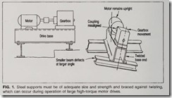
In the event that the motor must be mounted on steel, all supports must be of adequate size and strength and braced to assure maximum rigidity (Fig. 1).
Whether the motor base is concrete or steel, it must level. If concrete, be sure it is not too high . A foundation can always be raised by use of shims; but reduction of h eight would be diffi cult because it would require removal of some of the concrete surface.
The requireme nt for a level base is critical. Usually, for a motor installa tion, there will be four points of mounting-one at each corner of the mounting base. Th en there will be mounting requi rements for the driven load. All mou nting points must be on the exact same plane or the equipment will not be level. Th is is why a thick, rigid steel baseplate is preferred over an assembly of steel , or at least a steel baseplate should be used in conjunction with the steel assembly. For installa tion of large and heavy equipment, it is recommended that the services of a civil or mechanical engi neer be em ployed to assure proper installation.
Grouting and shimming
Proper grouting is of great impor tance to foundation stiff ness and sta bility. Even the best steel baseplate structures aren’t con sidered proper support u nless they are grouted in place. Fig. 2 shows an exaggeration of what may otherwise happen . Correct selection, mixing, and placement of grout is important , and suppliers of such material sh ould be con sul ted whenever this work is to be done. Th e accompanying ch eck list highl igh ts some important proper procedures.
Correct shimming is another essen tial to good motor/f oundation assem bly. It is as important as base design itself; yet it may get little attention. One way to assure a prope r shim installation is to physically remove and inspect the shims at every machine support just prior to fin al alignment.
Obvious problems with shims include rust, improper cut, fol ds and wrinkles.
burrs, hammer marks and dirt.
Remember why shims are used.
They’re not j ust to raise or lower the motor so shafts will line up. They also solve the basic geometry problem of insuring that all of the motor mount ing pads or feet are in one flat plane. Should any one of them be higher or lower than the others, and the motor feet are bolted down tightly to all, either the base or the motor frame will have to be warped out of line.
One useful test for the source of troublesome drive vibration is to loosen motor hold-down bolts one at a time while the motor is running. If vibration noticeably decreases, the trouble is probably due to a distorted base or improper shimming.
For shims to do the job, they must form a solid, tight pack when the bolts are tightened. A “spongy” set of shims means a loose joint , which may or may not stay planar with other mounting points.
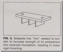
Another essential for a good founda tion is stability (Fig. 3). Once properly built and installed, the base has to remain that way. Excessive heat can be a problem. – For example, too much welding heat is one way to throw the base out of kilter. In severe hot outdoor climates, there have even been reports of steel bases “twisting” when desert sun impinged on one side while the other side remained in shadow. If the base is common to both motor and driven load, this might not be serious because both drive elements will see the same movement. Machinery connections such as heavy p1pmg, how ever, must allow for this hift in posi tion. If this isn’t feasible, a sun shade may be needed to equalize base heating.
For many drives, alteration of bases in the field has meant trouble. In one instance, a steel bedplate had been used for years with a particular motor-pump combination. To meet new operating conditions, a different, smaller motor was installed. Its shaft height was matched to the existing pump by welding supporting “posts” at the four corners of the old bedplate. These were strong enough to hold motor weight but were too flexible to keep the motor from vibrating back and forth. Moreover, the welds weren’t tight, so that one corner broke loose. Eventual result: bearing failure. At first, the problem was blamed on the motor; however, closer examination revealed the improper mounting methods that were used.
INSULATION STANDARDS AND APPLICATION OF MOTORS
Btandards for motor insulation sys Lems have been evolving in recent years to provide the most practical and effective method of specifying and applying motors. Latest insulation standards are based on specified test techniques that evaluate insulation based on simulated electrical, thermal, and mechanical stresses encountered by motors operating in actual service situations.
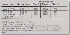
As a result, modern standards use a temperature-rise evaluation correlated to an ambient temperature of 40C. Values for various classes of insulating materials are determined by measure ment and calculation of resistance of motor windings. These insulation classes for integral-horsepower motors are listed in the accompanying table.
Note that Class A insulation is not listed, since it is no longer used in integral-hp motors. Also note that the service factor of the motor and encap sulation affect the insulation tempera ture rating.


