Insulation-resistance tests assure motor reliability
Insulatiort-r esistance testing plays a key role in a well-planned motor maintenance program for a large New York City skyscraper.
THE ELECTRICAL preventive mainte nance program at the world head quarters of the Equitable Life Assur ance Society of the United States is vital to continuous operation of electri cal systems serving thousands of people in this 42-story skyscraper.
An essential part of their program is the maintenance of hundreds of motors of various sizes and types. All critical motors, as well as those that are large, costly, and hard to replace, receive reg ular maintenance. Insulation-resist ance testing plays an important role in keeping these motors running.
For example, the air-conditioning systems for the huge building utilize several large motors ranging in size from 100 to 500 hp. A failure of one of these motors during a hot spell would result not only in personnel discomfort, but also in overloaded equipment, which would then become more vulner able to failure. To prevent this, any suspect motors are checked out during winter months.
In addition, several of the motors areno longer manufactured. This means that temporary replacement is next to impossible, and permanent replace ment would involve extensive changes to mounting arrangements, coupling to driven equipment, and changes in con trol equipment. This, of course, would result in an extended downtime and expensive replacement costs.
As a result, this equipme nt receives careful attention within the framework of the building electrical preventive maintenance program. Years of experience, coupled with accurate record keeping, has helped John Pensenhofer, chief electrician, to determine the most effective frequency of inspection and tests. For most motors as well as other important electrical equipment, inspec tions and tests are performed on an annual basis.
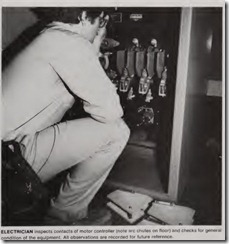
According to Pensenhofer, dirt, heat, moisture and vibration are arch ene mies of electrical equipment, and can do a great deal of damage to insulation, bearings, contacts and most moving parts. Therefore, the heart of their motor maintenance program is a visual inspection backed by insulation-resist ance tests.
Insulation test techniques
Insulation-resistance tests are car ried out using a battery-powered instrument that permits reliable, non destructive testing and evaluation of electrical equipment. The instrument is easy to use because it is pushbutton operated and provides for continuous testing without hand-cranking.
The electrical crew uses two basic insulation-resistance tests: a short time test, in which the resistance of the motor windings is checked quickly, and a comparative short-time test, which is done annually and which provides readings that are compared and evalu ated each year.
The short-time test is often per formed when it is desirable to obtain a quick evaluation of the condition of a motor. Usually three readings are taken-one from each phase of the motor to ground. If all three readings are above acceptable minimum values, the motor is considered operable for a preselected period of time (usualy six months to a year). Presently, the acceptable industry practice permits one megohn as the absolute minimum value of insulation resistance for a 460- volt motor. Minimum insulation resist ance normally should be somewhat higher-in the range of 20 to 50 megohms. However, acceptable values will vary in accordance with many fac tors, such as voltage rating of the insu lation, type of insulation, altitude, environment, and hp rating of the motor. Of particular significance are the effects of temperature, humidity and cleanliness of the area.
The comparative short-time test provides a highly reliable evaluation of the condition of the motor insulation.
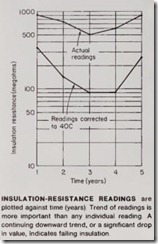
This technique is essentially the same as the short-time method except that readings are taken for a longer period of time; the instrument remains con nected for approximately 10 minutes each time a reading is obtained. Read ings usually vary in accordance with the length of time the instrument is connected. However, at the end of 10 minutes (which is an arbitrary length of time; 15 or 20 min could be used) the readings obtained usually reach a steady-state condition. On good, dry insulation, readings will normally climb slowly for about 10 min. If the insulation is damp or dirty, a steady state is usually reached quite soon after the test is started. All readings are taken annually and repeated for a period of years. Values thus obtained are charted, compared and interpreted, enabling a more accurate evaluation of the condition of the motor insulation. See accompanying illustrations.
Test procedure. At Equitable a team of two electricians carry out the test. Test procedures are directed by Jake Provost, senior electrician, who is often assisted by Anthony Faranda, plant electrician. First, Provost reviews all data on the motor to be checked. These records not only give him an idea of what to expect; they also warn of past problems and help him to prepare for safe, effective testing.
The accompanying photos and circuit diagram typify the testing of a 200- hp, 460-volt induction motor. The motor controller is a floor-mounted unit fur nished with an unfused disconnect switch and full-voltage contactors. Branch-circuit protection is provided by a 600-amp, molded-case circuit breaker installed in a nearby panel board.
Safety is a primary concern. Before connecting the instrument, the senior electrician makes certain that all equipment scheduled for the test is completely disconnected from all power sources. In this case, initial steps include the opening of both the circuit breaker and the disconnect switch.
Next, Provost uses a tester to make sure voltage is not present at the input terminals of the motor controller.
Because the tester can also serve as a voltmeter, he can set the instrument to read volts (see photo). Note that one lead of the tester is provided with a standard probe and the other with an alligator clip. The lead with the clip can be attached to the appropriate ter minal or ground. Thus, the electrician makes contact with the other insulated probe with only one hand in proximity to possibly energized equipment. He must be certain that voltage is not present before starting the insulation resistance test.
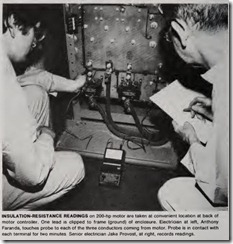
After all safety checks are com pleted, the insulation-resistance read ings can be taken at a point closest to the motor itself. In this instance, the most convenient point was at the back of the motor controller, where conduc tors from the motor come to the “load” terminals (see photo on opposite page).
Preceding the test, an “infinity” reading is checked with the instrument leads separated, followed by a “zero” reading with the leads shorted. This provides a check on the instrument accuracy.
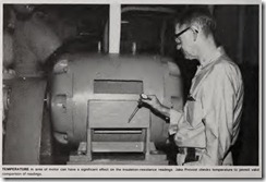
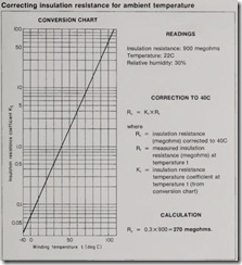
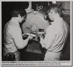
Next, the alligator lead is clipped to ground (frame of the controller), and a reading is taken at each motor lead terminal. The tester probe is placed in contact with each terminal for 10 minutes, after which the reading is recorded. In this case, the reading obtained on all three terminals was 900 megohms. This high reading is a strong indication that the motor insulation is in excellent condition. Ambient temperature readings and relative humidity readings are also taken and re corded, together with the conditions in the area-wet location, excessive dust or corrosion, presence of any chemical fumes, whether the motor had been running or had been at rest prior to the test. These factors have a significant effect on insulaton-resistance readings and aid in interpreting the readings.
The insulation-resistance readings are next corrected for ambient temper ature variations to a standard 40C. A temperature correction graph and sam ple calculations are provided in an accompanying illustration. (The cor rection formula, graph, and other help ful data are available in IEEE Recom mended Practice for Testing Insula tion Resistance of Rotating Machin ery-ANSI/IEEE Std 43-1974.)
All insulation-resistance readings are recorded annually on a time vs insulation-resistance graph. (Where three separate readings are taken, the lowest value is used.) Both the actual value and the value as corrected to 40C are entered on the graph. The readings are then plotted as shown. Insulation normally will show a slight decrease in resistance as it ages. The readings plot ted show a relatively fast decrease in the first three years, with a return to normal at the fifth year. There is no question that this insulation is good; variations in the readings may be caused by extensive clean-up of sur roundings, conditions when readings were taken, or a variation in test meth od. Had one of the readings dropped sharply to say 2 megohms, it would have indicated a possible-even proba ble-imminent insulation failure. In this event, additional investigation would be undertaken.
