The efficiency η has already been defined, both for motoring and generating, earlier in this chapter. The power factor cosϕ1 may be defined in relation to the equivalent circuit as
cosϕ =1 Ze (7.76)
Figure 7.9 shows that Re is negative for the actual generating mode. This explains why in (7.76) the absolute value of Re is used. The power factor, related to reactive power flow, has the same formula for both motoring and generating, while the efficiency needs separate formulas (7.50) and (7.53). The dependence of efficiency and power factor on load (slip or speed) is essential when the machine is used for variable load (Figure 7.20).
Figure 7.20 IM efficiency, η, power factor, cosϕ, and slip, S/Sn versus relative power load at the shaft: P2m/Pn
Such curves may be calculated strictly based on the equivalent circuit (Figure 7.1) with known (constant or variable) parameters, and given values of slip. Once the currents are known all losses and input power may be calculated. The mechanical losses may be lumped into the core loss resistance R1m or, if not, they have to be given from calculations or tests performed in advance. For applications with highly portable loads rated from 0.25 – to 1.5 the design of the motor has to preserve a high efficiency.
A good power factor will reduce VAR compensation hardware ratings and costs, as an industrial plant average power factor should not be lagging below 0.95 to avoid VAR penalties.
Example 7.5. Motor performance
An induction motor with deep bars is characterized by rated power Pn = 20 kW, supply line voltage Vsl = 380 V (star connection), f1 = 50 Hz, ηn = 0.92, pmec =
0.005 Pn, piron = 0.015 Pn, ps = 0.005 Pn, pcosn = 0.03 Pn, cosϕn = 0.9, p1 = 2, starting current Isc = 5.2In, power factor cosϕsc = 0.4, and no-load current Ion =
0.3In.
Let us calculate
a.) Rotor cage losses pcorn, electromagnetic power Pelm, slip, Sn, speed, nn, rated current In and rotor resistance Rr′, for rated load
b.) Stator resistance Rs and rotor resistance at start Rrs′
c.) Electromagnetic torque for rated power and at start
d.) Breakdown torque
Solution
a.) Based on (7.50), we notice that, at rated load, we lack the rotor cage losses, pcorn from all losses.
pcorn = ηPnn − (pcosn + pSn + piron + piron )− Pn = (7.77)
W
On the other hand, the rated current In comes directly from the power input expression
In A (7.78)
|
The slip expression (7.52) yields |
||
|
Sn = Pn −pcosnpcorn−pSn −piron ηn = 639.13 |
= = |
(7.79) |
0.0308
−(0.03+0.005+0.015 20000)
|
The rated speed nn is |
|
|
nn = Pf11 (1−Sn )= 502 (1− 0.0308)= 24.23rps =1453.8rpm The electromagnetic power Pelm is |
(7.80) |
|
Pelm = pcorn = 639.13 = 20739W |
(7.81) |
Sn 0.0308
To easily find the rotor resistance, we need the rotor current. At rated slip, the rotor circuit is dominated by the resistance Rr′/Sn and thus the no-load (or magnetizing current) I0n is about 900 behind the rotor resistive current Irn′. Thus, the rated current In is
Irn‘== 35.05A (7.83)
|
Now the rotor resistance at load Rr′ is |
|
|
R ‘r = pcornrn 2 = 3639⋅35..05132 = 0.1734Ω 3I ‘ b.) The stator resistance Rs comes from |
(7.84) |
Rs (7.85)
|
The starting rotor resistance Rrs′ is obtained based on starting data: |
|
|
R ‘= Vsl cosϕsc − R = 380 0.4 − 0.148 = 0.31186Ω |
(7.86) |
rs 3 Isc s 3 5.2⋅36.742
Notice that Kr (7.87)
This is mainly due to skin effect.
c.) The rated electromagnetic torque Ten is
Ten Nm (7.88)
The starting torque Tes is
Tes Nm (7.89)
T /Tes en =108.76/132.095 = 0.833
d.) For the breakdown torque, even with approximate formula (7.71), the short-circuit reactance is needed. From starting data,
Xsc = Vsl3 sinIscϕsc = 3803 5.21⋅−360.4.6722 =1.0537Ω (7.90)
The rotor leakage reactance Xrls = Xsc – Xsl = 1.0537 – 0.65 = 0.4037 Ω. Due to skin effect and leakage saturation, this reactance is smaller than the one “acting” at rated load and even at breakdown torque conditions. Knowing that Kr = 1.758 (7.87), resistance correction coefficient value due to skin effect, we could find Kx ≈ 0.9 from Chapter 8, for a rectangular slot.
With leakage saturation effects neglected the rotor leakage reactance at critical slip Sk (or lower) is
X ‘rl Kx X ‘ (7.91)
Now, with C1 ≈ 1 and Rs ≈ 0, from (7.71) the breakdown torque Tek is
Tek ≈ 3 Vsl 2 p
3 ω11 2(Xsl1+ X ‘rl ) = (7.92)
Nm
The ratio Tek/Ten is
Tek /Ten = 422.68 = 3.20
132.095
This is an unusually large value facilitated by a low starting current and a high power factor at start; that is, a low leakage reactance Xsc was considered.
PHASOR DIAGRAMS: STANDARD AND NEW
The IM equations under steady state are, again,
Is (Rs + jXsl )−Vs = Es
Ir ‘ R ‘r + jX ‘
Es= −S Z1m(Isrl+I+r ‘)VS= −r ‘ =Z1Em 0ssI
=
Z1m RR11mm+⋅ jXjX11mm = R1ms + jX1ms
R1m >> X1m; R1ms << X1ms; R1ms << R1m; X1ms ≈ X1m (7.93)
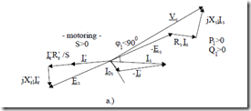
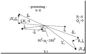
They can be and have been illustrated in phasor diagrams. Such diagrams for motoring (S > 0) and generating (S < 0) are shown in Figure 7.21a and b, for
Vr′ = 0 (short-circuited rotor).
As expected, for the short-circuited rotor, the reactive power remains positive for generating (Q1 > 0) as only the active stator current changes sign from motoring to generating.
PQ1 ==3V3Vs IssIcossinϕ <>ϕ >11 00 (7.94)
1
Today the phasor diagrams are used mainly to explain IM action, while, before the occurrence of computers, they served as a graphical method to determine steady-state performance without solving the equivalent circuit.
However, rather recently the advance of high performance variable speed a.c. drives has led to new phasor (or vector) diagrams in orthogonal axis models of an ac machine. Such vector diagrams may be accompanied by similar phasor diagrams valid for each phase of a.c. machines. To simplify the derivation let us neglect the core loss (R1m ≈ ∞ or R1ms = 0). We start by defining three flux linkages per phase: stator flux linkage Ψs, rotor flux linkage Ψr‘, and airgap (magnetizing) Ψm.
ψs = LslIs + ψm
ψr ‘= L ‘rl Ir ‘+ψm (7.95) ψm = L1m(Is + Ir ‘)= L1m Im
Es = − ωj 1L1m Im = − ωj 1ψm (7.96)
Figure 7.21 Standard phasor diagrams, a.) for motoring, b.) for generating
|
The stator and rotor equations in (7.93) become |
|
|
IsRs − Vs = − ωj 1ψs |
(7.97) |
|
Ir’ R ‘r + Vr ‘ = − ωj 1ψr ‘ |
(7.98) |
S S
For zero rotor voltage (short-circuited rotor), Equation (7.98) becomes:
Ir ‘ R ‘Sr = − ωj 1ψr ‘; Vr ‘= 0 (7.99)
Equation (7.99) shows that at steady state, for Vr′ = 0, the rotor current Ir′ and rotor flux Ψr′ are phase shifted by 900.
Consequently, the torque Te expression (7.60) becomes:
Te = 3R ‘I ‘rS r 2 ωp11 = 3p1ψr ‘I ‘r (7.100)
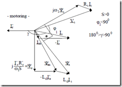
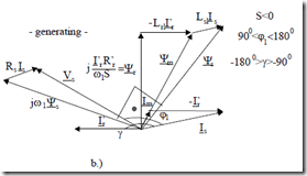
Equation (7.100) may be considered the basis for modern (vector) IM control. For constant rotor flux per phase amplitude (RMS), the torque is proportional to rotor phase current amplitude (RMS). With these new variables, the phasor diagrams based on Equations (7.97) and (7.98) are shown in Figure 7.22.
Such phasor diagrams could be instrumental in computing IM performance when fed from a static power converter (variable voltage, variable frequency).
Figure 7.22 Phasor diagram with stator, rotor and magnetization flux linkages, Ψr′, Ψm, Ψs
a.) motoring b.) generating (continued
Figure 7.22 (continued)
The torque expression may also be obtained from (7.97) by taking the real part of it after multiplication by Is*.
Re 3[ Is sI *Rs + 3jω1ψsIs*]= 3Re(V Is s*) (7.101)
The second term in (7.101), with core loss neglected, is, in fact, the electromagnetic power Pelm
|
Pelm = ω3 1 Imag(ψs Is*)= Te(ω1 /p1) |
(7.102) |
|
|
Te = 3p Imag1 (ψs Is*)= 3p L1 1m Imag(Ir ‘Is*) |
(7.103) |
|
|
or |
Te = 3p L1 1m Ir ‘Is sin ; γ γ > 900 |
(7.104) |
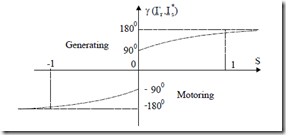
In (7.104), γ is the angle between the rotor and stator phase current phasors with γ > 0 for motoring and γ < 0 for generating.
Now, from the standard equivalent circuit (Figure 7.1 with R1m ≈ ∞),
Ir’= −Is R ‘Sr + ωjjω11(LL11mm + L ‘rl ) (7.105)
So the angle γ between Ir′ and Is* depends on slip S and frequency ω1 and motor parameters (Figure 7.23). It should be noted that the angle γ is close to ±1800 for S = ±1 and close to ±900 toward |S| = 0.
ALTERNATIVE EQUIVALENT CIRCUITS
Alternative equivalent circuits for IMs abound in the literature. Here we will deal with some that have become widely used in IM drives. In essence [2], a new rotor current is introduced.
Ira ‘= Iar‘ (7.106)
Using this new variable in (7.95) through (7.98), we easily obtain:
IsRs + ωj 1[Ls −aL1m ]Is −Vs = Ea
Ea = − ω ψj 1 ma; ψma = aL1m(Is + Ira ‘ ; ) Ima = Is + Iar ‘ (7.107)
Ira ‘R ‘ar 2 + ωj 1(aL ‘ Lr − 1m )aIra ‘+ V ‘aSr = Ea
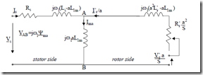
Figure 7.24 General equivalent circuit (core loss neglected)
For a = 1, we reobtain, as expected, Equations (7.95) through (7.98). Ls, Lr′ represent the total stator and rotor inductances per phase when the IM is threephase fed.
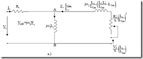
Now the general equivalent circuit of (7.107), similar to that of Figure 7.1, is shown in Figure 7.24. For a = 1, the standard equivalent circuit (Figure 7.1) is obtained. If a = Ls/L1m ≈ 1.02 – 1.08, the whole inductance (reactance) is occurring in the rotor side of equivalent circuit and Ψma = Ψs (Figure 7.25a). The equivalent circuit directly evidentiates the stator flux.
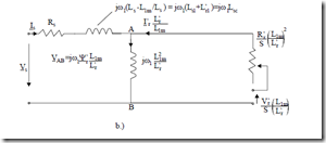
Figure 7.25 Equivalent circuit
a.) with stator flux shown b.) with rotor flux shown
For a = L1m/Lr′ ≈ 0.93 – 0.97, ψma = L L ‘1mr ψr ‘, the equivalent circuit is said
to evidentiate the rotor flux.
Advanced IM control is performed at constant stator, Ψs, rotor Ψr, or magnetization flux, Ψm amplitudes. That is voltage and frequency, Vs, f1, are changed to satisfy such conditions.
Consequently circuits in Figure 7.25 should be instrumental in calculating IM steady-state performance under such flux linkage constraints.
Alternative equivalent circuits to include leakage and main saturation and skin effect are to be treated in Chapter 8.
Example 7.6. Flux linkage calculations
A cage-rotor induction motor has the following parameters: Rs = 0.148Ω, Xsl = Xrl′ = 0.5Ω, Xm = 20Ω, 2p1 = 4poles, Vs = 220V/phase (RMS)–star connection, f1 = 50Hz, rated current Isn = 36A, cosϕn = 0.9. At start, the current
Istart = 5.8In, cosϕstart = 0.3.
Let us calculate the stator, rotor and magnetization flux linkages Ψs, Ψr′. Ψm at rated speed and at standstill (core loss is neglected). With S = 0.02, calculate the rotor resistance at full load.
Solution
To calculate the RMS values of Ψs, Ψr′. Ψm we have to determine, in fact, VAB on Figure 7.24, for as = Ls/L1m, ar = L1m/Lr′ and am = 1, respectively.
ψs 2 = 2 Vsω−1 IsRr (7.108)
ψr ‘ 2 = 2
|
V − I Rr − I jω1 Lsl + L ‘rl |
s s sL1m ( ) (7.109)
ω1 L ‘r
V
|
ω1 |
|
|
Is = I coss( ϕ − jsin ϕ) |
(7.111) |
ψm 2 = 2 s − IsRr − Is jω1Lsl (7.110)
These operations have to be done twice, once for Is = In, cosϕn and once for
Is = Istart, cosϕstart.
For In = 36A, cosϕn = 0.9,
ψs 2 = 2 220−36⋅(20.9π50− j4359)0.148 = 0.9654Wb
ψ ‘ 2 = 2 220−36⋅(0.9− j4359)(0.148+ j1) = 0.9314Wb (7.112) r 2π50 20
20.5
ψm 2 = 2 220 −36⋅(0.92π−50j4359)(0.148+ j1) = 0.9369Wb (7.113)
The same formulas are applied at zero speed (S = 1), with starting current and power factor,
(ψs 2)start = 2 220−36⋅5.8 0.32⋅(π50− j0.888)⋅0.148 = 0.9523Wb
(ψr ‘ 2)start = 2 220−36⋅5.8 0.32π⋅50( −20j0.888 )(0.148+ j1) = 0.1998Wb(7.114)
20.5
(ψm 2)start = 2 220−36⋅5.8 0.3⋅(2π50− j0.888)(0.148+ j1) = 0.5306Wb
The above results show that while at full load the stator, magnetization and rotor flux linkage amplitudes do not differ much, they do so at standstill. In particular, the magnetization flux linkage is reduced at start to 55−65% of its value at full load, so the main magnetic circuit of IMs is not saturated at standstill.
