Why Binary?
Arithmetically, the binary system is the simplest numbering scheme possible.
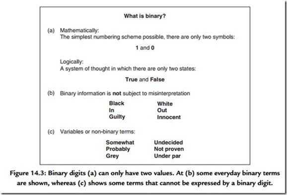
Figure 14.3(a) shows that there are only two symbols: 1 and 0. Each symbol is a binary digit, abbreviated to bit. One bit is a datum and many bits are data. Logically, binary allows a system of thought in which statements can only be true or false.
The great advantage of binary systems is that they are the most resistant to misinterpretation. In information terms they are robust. Figures 14.3(b) and 14.3(c) show some binary terms and some nonbinary terms, respectively, for comparison. In all real processes, the wanted information is disturbed by noise and distortion, but with only two possibilities to distinguish, binary systems have the greatest resistance to such effects.
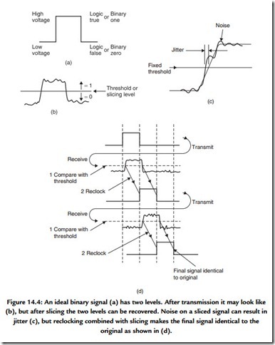
Figure 14.4(a) shows an ideal binary electrical signal is simply two different voltages: a high voltage representing a true logic state or a binary 1 and a low voltage representing a false logic state or a binary 0. The ideal waveform is also shown in Figure 14.4(b) after
it has passed through a real system. The waveform has been considerably altered, but the binary information can be recovered by comparing the voltage with a threshold that is set half way between the ideal levels. In this way any received voltage above the threshold is considered a 1 and any voltage below is considered a 0. This process is called slicing and can reject significant amounts of unwanted noise added to the signal. The signal will be carried in a channel with finite bandwidth, which limits the slew rate of the signal; an ideally upright edge is made to slope.
Noise added to a sloping signal [Figure 14.4(c)] can change the time at which the slicer judges that the level passed through the threshold. This effect is also eliminated when the output of the slicer is reclocked. Figure 14.4(d) shows that however many stages the binary signal passes through, the information is unchanged except for a delay. Of course, excessive noise could cause a problem. If it had sufficient level and an appropriate polarity, noise could force the signal to cross the threshold and the output of the slicer would then be incorrect. However, as binary has only two symbols, if it is known that the symbol is incorrect, it need only be set to the other state and a perfect correction has been achieved. Error correction really is as trivial as that, although determining which bit needs to be changed is somewhat harder.
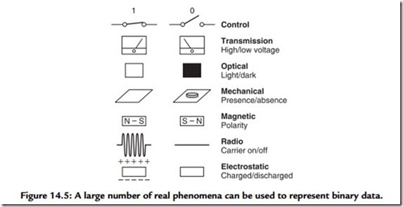
or closed and so represent a single bit. This switch may control the voltage in a wire that allows the bit to be transmitted. In an optical system, light may be transmitted or obstructed. In a mechanical system, the presence or absence of some feature can denote the state of a bit. The presence or absence of a radio carrier can signal a bit. In a random access memory (RAM), the state of an electric charge stores a bit.
Figure 14.5 also shows that magnetism is naturally binary as two stable directions of magnetization are easily arranged and rearranged as required. This is why digital magnetic recording has been so successful: it is a natural way of storing binary signals.
The robustness of binary signals means that bits can be packed more densely onto storage media, increasing the performance or reducing the cost. In radio signaling, lower power can be used.
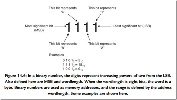
In decimal systems, the digits in a number (counting from the right, or least significant end) represent ones, tens, hundreds, thousands, and so on. Figure 14.6 shows that in binary, the bits represent one, two, four, eight, sixteen, and so on. A multidigit binary number is commonly called a word, and the number of bits in the word is called the wordlength. The right-hand bit is called the least significant bit (LSB), whereas the bit on
the left-hand end of the word is called the most significant bit (MSB). Clearly more digits are required in binary than in decimal, but they are handled more easily. A word of eight bits is called a byte, which is a contraction of “by eight.”
Figure 14.6 also shows some binary numbers and their equivalent in decimal. The radix point has the same significance in binary: symbols to the right of it represent one-half, one-quarter, and so on.
Binary words can have a remarkable range of meanings. They may describe the magnitude of a number such as an audio sample or an image pixel or they may specify the address of a single location in a memory. In all cases the possible range of a word is limited by the wordlength. The range is found by raising two to the power of the wordlength. Thus a 4-bit word has 16 combinations and could address a memory having 16 locations. A 16-bit word has 65,536 combinations. Figure 14.7(a) shows some examples of wordlength and resolution.
The capacity of memories and storage media is measured in bytes, but to avoid large numbers, kilobytes, megabytes, and gigabytes are often used. A 10-bit word has 1024 combinations, which is close to 1000. In digital terminology, 1 K is defined as 1024, so a kilobyte of memory contains 1024 bytes. A megabyte (1 MB) contains 1024 kilobytes and would need a 20-bit address. A gigabyte contains 1024 megabytes and would need a 30-bit address. Figure 14.7(b) shows some examples.


