The armature circuit has low resistance. When voltage is applied to it, a high inrush of amperes goes through the circuit. This gives the armature enough torque to rotate.
As the armature rotates, its conductors cut the lines of force of the shunt field. This action generates a counter-voltage in the conductors. The amperes of the armature are controlled by counter-voltage, the resistance of the wires, and the load.
As the armature gains speed, the counter-voltage increases and cancels more and more of the line voltage. As line voltage is canceled, amperes in the armature circuit go down. This is applying Ohm’s Law logic: When volts are lowered, resistance doesn’t change, and amperes decrease. At rated speed, only the amperes required by the load and the motor’s internal losses are needed. A 500-volt motor develops full power with all but 10 to 15 line volts canceled by counter-voltage.
Ninety-five to ninety-eight percent of the armature circuit’s potential current flow is canceled by counter-voltage. Without counter-voltage, high amperes and the resulting heat would destroy the armature. Unloaded, it would accelerate to a destructively high speed.
If the technician isn’t aware of counter-voltage, testing the armature circuit will be very confusing. If the nameplate voltage and amperes are used to find the resistance of the armature circuit, the actual resistance is much lower.
Base Speed
Base speed is the number of RPM at full load (with full voltage applied to the armature and field circuits). At base speed, the motor is putting out nameplate horsepower and RPM.
Below Base Speed
Below base speed is accomplished by controlling the current through the armature, with full voltage applied to the shunt field. With the shunt field fully energized, the motor has constant torque (from zero to base speed). Consequently, the motor’s horsepower output will increase as the speed increases.
This control is also used to start the motor.
Above Base Speed
The above base speed control is used after the motor has reached base speed, with full voltage applied to the armature circuit. As amperes are lowered in the shunt field, its magnetic field is weakened. A weaker magnetic field decreases the number of lines of force.
Fewer lines of force being cut by the armature conductors lowers the counter-voltage. Less counter-voltage allows more amperes to flow in the armature circuit. The motor accelerates to a speed above the original base speed and its speed is stabilized.
A weaker shunt field produces less torque, but with the increase in RPM, the motor still has the same horsepower. The control is also called above base speed control torque control or field weakening control.
The DC motor has constant torque below base speed and constant horsepower above base speed. These qualifications meet the demands of most loads.
Torque of the DC Motor
The DC motor has very good torque characteristics.
The commutator switches one circuit at a time in the armature slots. The slots contain one or more coils (circuits). As these coils are commutated, they control the magnetizing of the slot’s iron teeth. As the magnetism in the iron of the armature changes from north to south, it does so one tooth at a time, resulting in a very smooth torque at all speeds.
The Shunt Motor
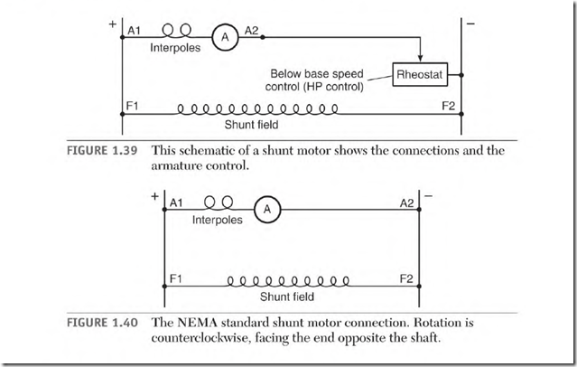
The shunt motor has two circuits: the armature and interpoles (Al and A2) and the shunt field (Fl and F2) (Fig. 1.39). (A current control for starting the armature is also illustrated.)
Figure I .40 shows the NEMA standard connection for counterclockwise rotation facing the end opposite the shaft.
The Armature and Interpoles
As shown earlier, the armature leads are identified as Al and A2. The armature windings produce all of the motor’s torque output. The interpoles ensure good commutation.
The Shunt Field
The shunt field leads are identified as Fl and F2. The purpose of a motor’s shunt field is to furnish magnetic poles for the armature poles to attract or repel and create torque.
Operation of the Shunt DC Motor
When a shunt motor is started, the shunt field is energized with full voltage. An armature control puts resistance in series with the armature circuit, limiting the amperes to a nondestructive level. The control allows
enough amperes through the armature to start the load. It then lowers the resistance until the motor accelerates to its selected speed.
If the shunt motor isn’t loaded, it will accelerate to its no-load speed when full voltage is applied to its circuits. At this speed, counter-voltage allows only the amperes needed for the armature’s losses. (This includes bearing friction, the cooling fan load, windage, and the armature circuit’s copper losses.) A shunt motor’s no-load RPM is higher than indicated on the nameplate.
As the load is applied to the shaft, the armature speed slows down. The armature conductors now cut fewer lines of force and create less counter-voltage. Less counter-voltage allows more amperes to flow in the armature circuit. The RPM will now stabilize at a lower speed. The load is then increased to the motor’s rated horsepower. At full load, the motor will operate at nameplate amperes and RPM.
 Starting a large DC motor with line voltage will cause excessively high amperes in the armature circuit and will damage the commutator.
If the shunt field disconnects or opens while the motor is running with no load, the armature will accelerate until it is destroyed. The armature will overheat if the motor is loaded and can’t accelerate. Without the magnetism of the shunt field, the armature develops very little counter-voltage. Only the resistance of the armature windings will limit the amperes.
