Service Operations
CLEANING THE SYSTEM
An examination of the cooling system for clean liness should be made periodically. The quickest way to do this is to scrape a finger around the inside of the radiator filler neck and if an accumu lation of rust or oily muck is brought forth, the system should be cleaned.
The color of the cooling liquid can be conven iently checked by drawing a sample into a suit able hydrometer or anti-freeze tester. The appear ance of rust in the sample is an indication that either the corrosion inhibitor has lost its effective ness, or the system was not treated with an inhibi tor. Rusty water or anti-freeze solution should be drained and discarded. Following the draining, the system should always be cleaned before fresh coolant is installed.
To clean the system, remove the radiator cap to let in air so that the system will drain faster. Then open all drain cocks, leaving them open until the system is completely drained. Draining points are at the bottom of the radiator, on the side of the cylinder block and, in some cases, under the water pump.
If the car is equipped with a hot water heater, drain it also. If the heater is mounted on the dash, disconnect the hose at the lower heater connection. If the heater is under the seat, remove one hose at the heater and disconnect the other at the engine block. To empty the heater completely, apply a little compressed air to the connection at the engine.
After emptying the system, close all drains and reconnect the heater hose. Add the correct amount of good cleaning compound (instructions printed on container) and fill the system with water. Be sure the water level is low enough so that the solution will not be lost out of the overflow pipe.
Run the engine at a fast idle for at least 30 minutes after the cleaning solution has heated up. Then drain the solution and, if the cleaning com pound used is one that requires a neutralizing agent after its use, add the neutralizer and fill the system with water. Run the engine for at least five minutes after the neutralizing agent has heated up, then dra\n it out and refill with fresh water. Again run the engine for a few minutes to wash out the neutralizing agent and drain the system. Finally, refill with fresh water and corrosion in hibitor or with the proper anti-freeze solution, depending on the season.
During the engine idling periods, it is important to cover the radiator and keep the cover adjusted so that a temperature of 180 to 200 degrees is maintained. The engine develops so little heat while running without load that the thermostat valve remains partially or fully closed. Covering the radiator opens the valve quickly; but if the cover is removed the valve will close again, even though the temperature shows little change. It is a good idea to remove the thermostat during the cleaning operation to be sure the system is not being restricted. ‘
As a part of the cleaning operation, sediment and foreign matter should be removed from the radiator pressure cap valves (if fitted), the over flow pipe and radiator core air passages.
To check for a clogged radi tor overflow pipe, fill the radiator to the top of the filler neck and if it fails to flow through the overflow pipe, it is clogged. Usually the obstruction can be cleared out by pushing a length of iron wire down through the pipe. Any deposits embedded in the lower end of the pipe may be reached by poking the wire through the bottom opening. Of course, this should be checked before the cleaning opera tion, but in the event that it was forgotten, be sure to drain off the excess water from the radiator to bring it down to the proper level.
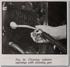
Dirt and insects may be cleaned out of the radiator air passages by applying a radiator core cleaner gun to the back of the core, Fig. 44. If such equipment is not available, wet the outside
surfaces of ·the radiator core until all foreign matter is thoroughly saturated. Then direct a stream of water through the air passages from the engine side of the core until all passages are free.
FLUSHING THE SYSTEM
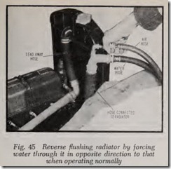
Cooling systems so badly clogged that they do not respond to the above treatment should be reverse Bushed, using air pressure to force the water through the system. Reverse flushing is just what the name implies-Bushing in the direction opposite to the normal Bow of water through the system. Reverse Bushing is used to get behind the corrosion deposits to force th em out.
First remove the thermostat, as cold water will cause it to close and result in building up pressure which might cause damage. Then remove the upper and lower hose connections and replace the radiator cap. Attach a lead-away hose at the top of the radiator and a piece of new hose to the radiator outlet connection. Insert the flushing gun in this hose, Fig. 45. Connect the water hose of the flushing gun to a water outlet and the air hose to an air line. Turn on the water and when the radiator is full, turn on the air in short blasts, allowing the radiator to fill between blasts of air. Continu e in this manner until the water from the lead-away hose runs clear. Be sure to apply the air gradually as a clogged radiator will stand only a limited pressure.
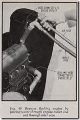
After flushing the radiator, attach the lead away hose to the water pump inlet and a length of new hose to the water outlet connection at the top of the engine. Insert the flushing gun into the new hose, Fig. 46. Tum on the water and when the engine water jacket is full, apply the air in short blasts. Continue this sequence until the water from the lead-away hose runs clear.
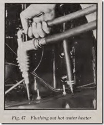
If the car has a hot water heater, it should be flushed out separately, Fig. 47, as rust deposits will built up in the heater core just as they do in the radiator. If flushing is done in the spring and the heater will not be used until the fall, it is wise to discard the heater hose. If the flushing is being done in the fall, replace the hose.
ANTI-FREEZE PROTECTION
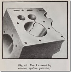
When water freezes it forms solid ice and ex pands approximately 9 per cent in volume. This expansion takes place with a terrific force and if allowed to take place in the cooling system, the force of the expansion will crack the engine water jacket, Fig. 48, and cause serious damage to the radiator and other parts.
The amount of anti-freeze required depends upon the capacity of the cooling system, the lowest temperature likely to be encountered, and the type of anti-freeze to be installed. For ex ample, if the cooling system capacity is 20 quarts, 6 quarts of methanol (alcohol) protects to 5 de grees below zero; but 6 quarts of permanent type protects to 4 degrees above zero. Anti-freeze makers supply their dealers with charts which give full information for all makes and models of vehicles.
To install anti-freeze, first drain the system completely. Then pour in enough water to half fill the cooling system. Add the required amount of anti-freeze and finish filling with water. Start the engine and run it for a few minutes. This allows the solution to mix thoroughly and permits the thermostat to open, which will release any trapped air that may be in the engine block. Be sure the level of the solution is low enough to allow for expansion, and check the system for leaks nd recheck level before putting the car in service.
TESTING ANTI-FREEZE
To be sure the anti-freeze will give protection at the coldest temperature to which the engine is likely to be exposed, and to avoid overheating difficulties from slush freeze-up, the freezing pro tection of the solution should be tested at least weekly and more often if the need is indicated because of water additions or weather conditions.
Always use a good hydrometer for checking the strength of anti-freeze solution. The accuracy of the hydrometer should be checked occasionally by taking readings on prepared solutions of known freezing point. Before reading the hydrometer, the barrel should be filled and emptied several times in order to equalize the temperature of all parts. Accurate readings cannot be obtained if the float and inside of the glass barrel are dirty.
When taking a sample of the solution, if the level has dropped to a point where the hydrom eter cannot reach it, drain a small quantity of the solution into a clean glass jar and make the test from the jar. After testing, pour the solution back into the radiator and add the necessary amount of anti-freeze to give the proper protection. If neces sary, add water to the proper level and then check the system for leaks with the engine running and when not running.
It is well to note that alcohol type anti-freeze solutions will boil away if the engine overheats. If the car has a pressure cap and if there is no leakage in the cooling system, add alcohol to bring the coolant up to its proper level. On the other hand, if ethylene glycol is used and the engine overheats, only water will boil away. Therefore, water should be added to bring the level up to normal.
USE OF HYDROMETER
An hydrometer is used to determine at what temperature the coolant will freeze. There are a number of them on the market, one of which is shown in Fig. 49.
The hydrometer float consists of a glass tube which is weighted at the bottom so that it will float upright as shown. Obviously, the lighter the liquid, the lower it will sink and the heavier the liquid the higher it will ride.
Methanol is 60 per cent as heavy as water, while ethylene glycol is 11.5 per cent heavier than water. Consequently, the scale on the hydrometer float indicates the amount of anti-freeze in the coolant.
Liquids expand and become lighter as their temperature rises. Consequently, it is necessary to know the temperature of the coolant when read ing an hydrometer. Therefore, the device is equipped with a thermometer.
For example, with ethylene glycol, if the level of the liquid is at E, Fig. 49, and the temperature is 160 degrees, the table on the hydrometer shows that there is 50 per cent ethylene glycol in the coolant. However, if the level of the liquid is at E and the coolant temperature is 50 degrees, there is only 20 per cent ethylene glycol in the coolant.
Similarly, when using this hydrometer to determine the amount of methanol in the coolant, if the level of the liquid is at J, Fig. 49, it means that 15 per cent of the coolant is methanol if its tempera
ture is 160 degrees but that nearly 40 per cent is methanol if its temperature is 50 degrees. All this may sound very complicated. However, the direc tions on the hydrometer make the temperature problem quite simple.
To use the hydrometer shown, you first look up the capacity of the cooling system of the car. This information is given in a compact table on the back of the device. The capacity figures are for cars without heater. The directions recommend that 2 quarts be added if the car has a heater. Let us assume that the capacity with heater is 20 quarts and that zero protection is desired.
There are four anti-freeze tables inside the housing and any one of them can be brought into position by turning the knurled wheel.
The next step is to fill the hydrometer with coolant. Insert the rubber tube in the filler neck. Squeeze the bulb hard and release it to draw liquid up into the chamber containing the hy drometer float. Adjust the liquid level by operat ing the bulb so that the hydrometer float floats freely and does not touch either at the top or the bottom. Be sure to hold the hydrometer vertical when reading it.
Let us assume that the coolant level is at E, Fig. 49, and that the coolant temperature is 120 de grees. Now assume that protection is wanted down to 20 degrees below zero. A table on the housing of the hydrometer shows that 3 quarts of anti-freeze should be added. Draw 4 or 5 quarts from the radiator into a pail. Pour 3 quarts out of the pail and throw away. Add 3 quarts of anti freeze directly into the cooling system and pour the contents of the pail back into the radiator.
With this hydrometer the coolant can be checked at any temperature between 55 and 160 degrees.
HOSE INSPECTION
If the outside of the hose is hard, cracked or rotted, install new hose. When cylinder head or radiator has been removed, inspect inside of hose for cracks and loose rubber which has separated from the fabric. If there are any loose flaps of rubber or if portions of the rubber surface have been torn off and carried away, hose should be renewed. When in doubt as to hose condition, install new hose. If one hose connection does not pass inspection, renew all hose to avoid future trouble.
HOSE, REPLACE
Apply a coat of water-proof gasket cement to the metal connections. Install the hose. Install the , hose clamps and tighten them securely. The gasket cement not only is insurance against leak age but also acts as a lubricant which makes hose installation easier. When installing a hose, never use grease as a lubricant as it will rot the rubber.
DRIVE BELTS
Fan belts and other driving belts should be re placed when they begin to show wear. Belts are designed to contact the sides of their pulleys and should not touch the bottom of the pulley groove.
The sides of the pulley should have a polished appearance because of belt contact but if the bottom of the groove is polished it indicates that the felt does not fit properly or is much too tight. To be on the safe side a new belt should be installed.
A belt should be replaced when it becomes frayed. Before installing the new belt examine the sides of the pulleys for rough spots. If any are found, replace the pulley or smooth it up with fine emery cloth. A pulley with a broken flange should be discarded.
Pulleys at all times should be kept free of oil and grease because lubricants may cause the belt to slip, may pick up dirt that will soon fray the belt or may ruin the belt by softening the rubber used in its construction.
Belt Adjustments
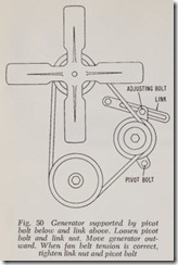
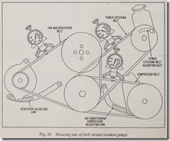
Fig. 50 illustrates the most common fan generator-water pump belt arrangement, while Fig. 51 shows a typical belt set-up when air conditioning and power steering are involved. The adjustment links and slots shown are in general use on most cars.
Precise adjustment of drive belts is a must.
Loose adjustment of fan-generator belts may cause overheating and low generator output; slip page of the power steering pump belt may not provide adequate oil pressure, and slippage of the air conditioner compressor belt may not provide enough pressure for proper operation of the sys tem. Too tight adjustments wear belts prema turely and causes early failure of shafts and bear ings in the driven units.
Car manufacturers stress the importance of proper belt adjustments and almost all of them recommend the use of a belt strand tension gauge, Fig. 51. The gauge is placed midway on the belt as shown. Then the belt is adjusted until the proper tension is indicated on the gauge. In the example shown, the fan-generator belt is adjusted to 60 lbs, the power steering belt to 80 lbs, and the compressor belt to 72lbs.
If such a gauge is not available, general practice is to adjust a belt of ordinary length so it has a deflection of W’ at its midway point; longer belts would require a greater deflection, say 3/4″ to 1″.
RADIATOR FLOW TESTER
A radiator flow tester measures the maximum How of water through the radiator in gallons per minute. The device consists of an open test tank filled with water, a variable speed pump driven by an electric motor, and a meter which registers the How in gallons per minute. The radiator can be tested either on the car or off.
A hose from the pump is connected to the lower radiator outlet. Water is pumped upward through the radiator and flows out of the top radiator inlet. If the radiator is off the car, water spills out and falls into the test tank. If the radiator is on the car, a hose is connected to the top radiator inlet so that the water issuing from it is returned to the tank.
With the radiator cap removed, the pump speed is increased until the water level in the radiator rises until it is even with the top of the overflow tube. Then the meter is read to determine the flow in gallons per minute. The operator then refers to a table which gives the flow rate for all makes and models of cars. If the flow rate is much less than normal the radiator should be cleaned. The radi ator How is tested again after cleaning to make sure that flow is normal.
WELCH PLUG, RENEW
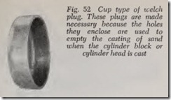
Welch plugs are used to seal holes in cylinder block or cylinder head which were necessary in connection with making the casting.
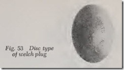
A leaky welch plug, Figs. 52 and 53, should be replaced by a new one. To remove it, punch or drill a hole (about 3/8″) in its center. Insert a punch or rod in the hole and pry out the plug. Clean away any rust or dirt from the sides of the hole. Apply a waterproof gasket cement to the sides of the hole and to the edges of the plug. Insert the plug in the hole with the curved top toward you. Press or tap it in as far as it will go. To lock it in place, expand it by hitting its center with a hammer and drift. The drift should be about half the diameter of the hole.
If a welch plug is located at the rear of the cylinder block, it may be necessary to remove the engine to get at it. Some mechanics cut a large hole in the dash panel in order to reach the plug. Special “hole saws” are used for this purpose al though their primary purpose is to cut holes in instrument panels to mount instruments.
If a hole saw is not available and if it is not feasible to remove the engine for economic or other reasons, the leak may be stopped by pouring a stop-leak compound in the cooling system.
STOP-LEAK COMPOUNDS
Although stop-leak compounds are usually effective in curing small leaks at least temporarily, they cannot be depended upon to correct leakage which involves combustion pressures at the cylin der head and cylinder head gasket.
There are a number of brands of stop-leak compound in either liquid or powder form. Bring the engine up to normal operating temperature and pour a specified amount in the filler neck opening, according to the directions on the can or package.
Continue to run the engine 15 minutes or so until the leaks are sealed. Stop-leak compound remains liquid when in the coolant but as soon as it is exposed to air at the point of leakage it congeals.
In the case of a large leak, two doses may be required. If this fails to stop the leak, the leak is too large and should be repaired.
If the cooling system is subsequently drained and if there is stop-leak in the system, it should be given a new dose of stop-leak when it is refilled.
If a cooling system with a pressur cap boils there may be slight leakage through the cracks as long as the system is under pressure. But the leakage should stop as soon as boiling ceases and
pressure falls to zero.
WATER PUMP SERVICE
Water pumps rarely give trouble and, therefore, it is not often that a pump has to be overhauled or repla ced with a new or rebuilt one.
The principal trouble i leakage of water. If the leakage is at the gasket between the pump and the cylinder block, the remedy, of course, is to install a new gasket after cleaning the metal surfaces which mate with the gasket. Many pumps also have a gasket and cover, and leakage may require a new gasket. However, in both the cases just mentioned the leakage may be due to loose bolts or nuts; therefore, tightening them may cure the leakage, thus making the removal of the pump unnecessary. When renewing water pump gaskets it is recommended that both sides of th e gasket be coated with a waterpro of gasket cement before gasket installation. Note that the use of a stop-leak compound may make renewal of the gaskets un necessary.
If there is leakage at the seal it is necessary to overhaul or replace the pump. The leakage may be due to worn seal parts or to worn bushings or bearings. (A badly worn ball bearing will be noisy.) Not only does water leak out of the seal but also when the pump is ope’rating at high speed its suction may draw air into the cooling system. The air bubbles in the water may reduce the effectiveness of the system and produce over heating.
Leakage at the pump may also be due to blow holes in the pump body or to a crack caused by a severe freezing. In most cases this leakage can be cured by putting a stop-leak compound into the radiator.
Water Pump Removal
Drain radiator. Remove hose connections to water pump. Loosen fan belt adjustment and re move belt. Remove fan blades. Remove bolts or nuts holding pump to cylinder block and take off pump and gasket. If the pump has a cover remove it and its gasket. If car has a fan shroud it may be necessary to loosen or remove it to get the fan out.
It seems hardly necessary to remind the reader that if there are any other parts in the way of pump removal they must be taken off. For exam ple, it may be necessary to remove oil filter pipes. And on cars with power steering the hydraulic pump may have to be removed. And the engine support bolts removed if there is insufficient space between the pump and radiator to permit removal of the water pump. In some cases, the engine may have to be jacked up to provide clearance be tween the water pump and the engine support bolts before the pump can be removed. In any event, a careful inspection of the area around the water pump should disclose what additional work has to be done.
Water Pump Repairs
For water pumps, suitable pullers and drifts are required. An arbor press is practically a must to push parts off and on. On some pumps with bushings, a burnishing tool is recommended to give the bushings the desired inside diameter and surface finish although a reamer may be used instead.
Most water pumps have the following features in common as shown by the accompanying pictures:
The front end of the shaft drives the fan hub. The rear end of the shaft drives the pump impeller.
To prevent leakage of water at the shaft, there is a seal assembly between the pump body and the impeller hub.
The seal assembly includes a spring-backed seal ring which prevents leakage by either pressing
against the impeller hub or the pump body, de pending on the construction. On some pumps, the seal ring rotates with the impeller. On others it is stationary.
Some pumps have covers while others do not.
The pump shaft is mounted on three types of bearing arrangements as shown in the pictures. These are: a sealed bearing with two rows of balls; two bushings; one bushing with a sealed bearing with one row of balls. In a sealed bearing the lubricant is sealed in at the time of manufac ture and should last for the life of the pump. Bushings require occasional lubrication and, therefore, are provided with a grease fitting. The sealed bearing and the shaft are sold as a unit, since the inner races for the balls consist of grooves in the shaft.
Before taking the pump apart, note that when the pump is put back together again the impeller and fan hub must be correctly positioned on the shaft-exactly as they were before they were dis assembled. Therefore, before removing the fan hub, measure the distance from the fan hub to the front end of the shaft. Likewise, measure the distance from the impeller hub to the rear end of the shaft. These measurements should be written down so they won’t be forgotten. Of course, if the fan hub and impeller hub are flush with their respective shaft ends, there is no problem. The impeller hub is usually flush with the end of the shaft but not always. The fan hub may or may not be flush. In some cases one or both hubs may be almost flush. It is particularly important to have the impeller accurately positioned on its shaft as otherwise it may rub against the pump body or its cover. After installing the impeller, check the clearance between the impeller and pump body with a feeler gauge. It should be at least .010″. If the pump has a cover, be sure the impeller does not rub against the cover. If it does, more clearance is required.
After the pump has been disassembled, its parts should be thoroughly cleaned. However, do not allow any solvent to touch a sealed bearing as the solvent may get into the bearing and render the lubricant therein useless. Rubber seal parts may also be damaged by solvent. A complete new seal assembly should be installed, regardless of the condition of the old seal.
Rotate the sealed bearing on its shaft. If there is any indication of sticking or grinding or if there is excessive play, install a new shaft and bearing assembly.
If the shaft rotates in bushings, renew the bush ings and shaft if there is noticeable side play. Renew the shaft if it is scored or corroded where it rotates in the bushings. The shaft should be dipped in light engine oil before installing. Be sure to fill the lubricant chamber with water pump grease.
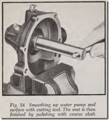
Before installing the pump shaft, examine the surface against which the seal ring presses. This surface is either the front of the impeller hub or on the adjacent pump body. If the surface is rough it should be smoothed up with a facing tool of the type shown in Fig. 54, and finished with crocus cloth. If the seal surface is so badly dam aged that a good refacing job cannot be obtained, renew either the impeller or the pump body, whichever is necessary.
Inasmuch as water pumps are usually replaced with new or rebuilt units, the following para graphs will deal with the overhaul of one typical unit.
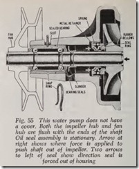
Disassemble Fig. 55 Pump
Remove snap ring.
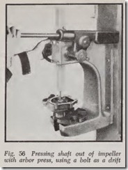
Press shaft out of impeller by applying force as shown by the arrow at right, Fig. 55. Fig. 56 shows how an arbor press is used to press the shaft out.
Press the fan hub from the shaft, if necessary.
With shaft and bearing and impeller out of the way, press seal assembly out of pump body to the right as shown by the arrows, Fig. 55.
Assemble
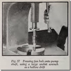
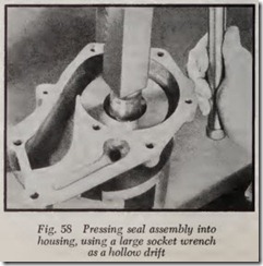
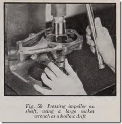
Press fan hub on shaft, Fig. 57, until it is flush with end of shaft. Install n ew seal assembly by pressing it in place, Fig. 58. Install shaft and sealed bearing by means of a hollow drift which presses on’ th e outer race of the bearing. Align snap ring groove in bearing with groove in pump body and install snap ring. Press impeller onto end of shaf t, Fig. 59, until it is flush with end of shaf t .
RADIATOR REMOVAL
The bottom of the radiator is usually bolted to the front cross member of the frame or to brackets attached to the frame. If there are spacer washers between the bottom of the radiator and its sup port be careful to install the same number of washers on each bolt when putting the radiator back on. In some cases there are brackets at the sides of the radiator to support it.
If the battery is at the side of the engine, dis connect the battery ground strap at the battery. Otherwise, if the radiator slips while removing or replacing it and touches the live battery terminal, the radiator may be seriously damaged.
Before starting to remove the radiator, look the engine compartment over carefully to determine what is in the way. Remove fan blades if they are in the way although on some cars it is sufficient to rotate the fan blades by hand so that th ey will not interfere with the radiator outlet while lifting the radiator out. When the radiator is disconnected and all is clear otherwise, lift up the radiator and swing it back over the top of the engine.
Review Questions
|
1. |
What is the purpose of a cooling system? . . . . . . . . . . . . . . . . . . . . . . . . . . . . . . . . . . . . . . . . . . |
|
2. |
What is the proper name of the liquid in a cooling system? . . . . . . . . . . . . . . . . . . . . . . . . . . . . |
|
3. |
Name the major compon ents of a cooling system. . . . . . . . . . . . . . . . . . . . . . . . . . . . . . . . . . . . . |
|
4. |
Most thermostats operate in what temperature range? . . . . . . . . . . . . . . . . . . . . . . . . . . . . . . |
|
5. |
What is the most common location of the water pump on an automobile engine? . . . . . . . . |
|
6. |
What type of water pump is always used in the cooling system? . . . . . . . . . . . . . . . . . . . . . . |
|
7. |
Describe the general direction of flow in a cooling system. . . . . . . . . . . . . . . . . . . . . . . . . . . . . |
|
8. |
What is the main advantage of using a pressure type radiator cap? . . . . . . . . . . . . . . . . . . . . |
|
9. |
What is the purpose of the vacuum valve on a radiator pressure cap? . . . . . . . . . . . . . . . . . . |
|
10. |
Name two types of thermostats. . . . . . . . . . . . . . . . . . . . . . . . . . . . . . . . . . . . . . . . . . . . . . . . . . . |
|
11. |
What are three methods which might be used to operate the valve on a thermostat? . . . . . . |
|
12. |
What is a thermostat bleed hole? . . . . . . . . . . . . . . . . . . . . . . . . . . . . . . . . . . . . . . . . . . . . . . . . . . |
|
13. |
What is ambient air temperature? . . . . . . . . . . . . . . . . . . . . . . . . . . . . . . . . . . . . . . . . . . . . . . . . |
|
14. |
What type of anti-freeze must be used with a thermostat that opens at a temperature higher than 160° F? ……………. ………. ……….. ….. · · .. ·.· ··……… |
|
15. |
How does thermostat operation govern the effectiveness of a hot water type heater? . . . . . . |
16. Explain the difference between a choke type and a by-pass type temperature control system. . . . . . . . . . . . . . . . . . . . . . . . . . . . . . . . . .
17. How can it be determined whether or not the thermostat is being installed right side up?
18. Either of what two types of radiator hose should be used when the outlets to be connected are not in a straight line? . . . . . . . . . . . . . . . . . . . . . . . . . . . . . . . . . . .
19. What is the principal difference between the cooling system of the Corvair and that of conventional cars? . . . . . . . . . . . . . . . . . . . . . . . . . . . . . . . . . . . . . . . . . . . . . . .
20. How does altitude affect the boiling point of water? . . . . . . . . . . . . . . . . . . . . . . . . . . . . . . . .
21. Explain why it is especially important to have a pressurized cooling system on cars that operate in mountainous country? . . . . . . . . . . . . . . . . . . . . . . . . . . . . . . . . . . . . . .
22. Name the main reason why modem water pumps have curved impeller blades. . . . . . . .
23. What particular additive is common to all types of anti-freeze? . . . . . . . . . . . . . . . . . . . . .
24. Ethylene glycol is the main ingredient in what type of anti-freeze? . . . . . . . . . . . . . . . . . .
25. Would pure ethylene glycol in the cooling system give the most anti-freeze protection in cold weather? . . . . . . . . . . . . . . . . . . . . . . . . . . . . . . . . .
26. Name two adverse effects of overheatin g.
27. Name two adverse effects of overcooling.
28. Most of the solid matter that clogs up radiators originates in what part of the cooling system? . . . . . . . . . . . . . . . . . . . . . . . . . . . . . . . . . . . . . . . .
29. Besides inadequate cooling, what harm does low coolant level in the radiator do to the en gine? . . . . . . . . . . . . . . . . . .
30. In what respect does rust formation in the radiator affect cooling system operation? . . . .
31. What is the prime function of the radiator? . . . . . . . . . . . . . . . . . . . . . . . . . . . . . . . . . . . . . . .
32. At what points is a leak in the cooling system most likely to occur? . . . . . . . . . . . . . . . . . .
33. Name two adverse results of exhaust gases being blown into the cooling system. . . . . . . .
34. How does a leaking water pump increase corrosion in the cooling system? . . . . . . . . . .
35. What is the most common type of malfunction in a water pump? . . . . . . . . . . . . . . . . . . . . .
36. Is it good practice to remove the thermostat f or Summer driving? . . . . . . . . . . . . . . . . . . . . . .
37. What could be expected to happen if a fan belt were over-tightened? . . . . . . . . . . . . . . . .
38. Describe two simple tests for checking thermosta t operation . . . . . . . . . . . . . . . . . . . . . . . . .
39. Describe a simple test for a clogged radiator core. . . . . . . . . . . . . . . . . . . . . . . . . . . . . . . . . .
40. What is the best way to thaw out a frozen cooling system? . . . . . . . . . . . . . . . . . . . . . . . .
41. What are the two most likely causes of foaming of the coolant? . . . . . . . . . . . . . . . . . . . . . .
42. What is the most common cause of combustion leaks into the cooling system? . . . . . . . . . .
43. List the items that would be needed to test a thermostat. . . . . . . . . . . . . . . . . . . . . . . . . . . . .
44. Why is the term “reverse Hush” used to denote this particular type of cooling system service? . . . . . . . . . . . . . . . . . . . . . . . . . . . . . . . . . .
45. Why does water burst cylinder blocks and radiators when it turns to ice? . . . . . . . . . . . .
46. What is the necessity for a thermometer on an anti-f reeze hydrometer? . . . . . . . . . . . . . . .
47. What substance must never be used to facilitate hose installation? . . . . . . . . . . . . . . . . . . . .
48. Why do some cylinder heads and all cylinder blocks have holes which make welch plugs necessary? . . . . . . . . . . . . . . . . . . . . . . . . . . . . . . . . . . . . . . . . . . . . . . . .
49. How is a leaking welch plug replaced? . . . . . . . . . . . . . . . . . . . . . . . . . . . . . . . . . . . . . . . . . . . .
50. On most water pumps, what parts of the cooling system are attached to each end of the pump shaft? . . . . . . . . . . . . . . . . . . . . . . . . . . . . . . . . . . . . . . . . . . . . . . . . . . . . . . . . . . . . . . .
