SHUNT, SERIES AND COMPOUND MOTORS
Before variable-voltage supplies became readily available, most d.c. motors were obliged to operate from a single d.c. supply, usually of constant voltage. The armature and Weld circuits were therefore designed either for connection in parallel (shunt), or in series. As we will see shortly, the operating characteristics of shunt and series machines diVer widely, and hence each type tends to claim its particular niche: shunt motors were judged to be good for constant-speed applications, while series motors were (and still are) widely used for traction applications.
In a way it is unfortunate that these historical patterns of association have become so deep-rooted. The fact is that a converter-fed separately excited motor, free of any constraint between Weld and armature, can do everything that a shunt or series motor can, and more; and it is doubtful if shunt and series motors would ever have become widespread if variable-voltage supplies had always been around. Both shunt and series motors are handicapped in comparison with the separately excited motor, and we will therefore be well advised to view their oft-proclaimed merits with this in mind.
The operating characteristics of shunt, series and compound (a mixture of both) motors are explored below, but Wrst we should say some- thing of the physical diVerences. At a fundamental level these amount
to very little, but in the detail of the winding arrangement, they are considerable.
For a given continuous output power rating at a given speed, we Wnd that shunt and series motors are the same size, with the same rotor diameter, the same poles, and the same quantities of copper in the armature and Weld windings. This is to be expected when we recall that the power output depends on the speciWc magnetic and electric loadings, so we anticipate that to do a given job, we will need the same amounts of active material.
The diVerences emerge when we look at the details of the windings, especially the Weld system, and they can best be illustrated by means of an example which contrasts shunt and series motors for the same output power.
Suppose that for the shunt version the supply voltage is 500 V, the rated armature (work) current is 50 A, and the Weld coils are required to provide an MMF of 500 ampere-turns (AT). The Weld might typically consist of say 200 turns of wire with a total resistance of 200 V. When connected across the supply (500 V), the Weld current will be 2.5 A, and the MMF will be 500 AT, as required. The power dissipated as heat in the Weld will be 500 V x 2:5A ¼ 1:25 kW, and the total power input at rated load will be 500 V x 52:5A ¼ 26:25 kW.
To convert the machine into the equivalent series version, the Weld coils need to be made from much thicker conductor, since they have to carry the armature current of 50 A, rather than the 2.5 A of the shunt motor. So, working at the same current density, the cross section of each turn of the series Weld winding needs to be 20 times that of the shunt Weld wires, but conversely only one-twentieth of the turns (i.e. 10) are required for the same ampere-turns. The resistance of a wire of length l and cross-sectional area A, made from material of resistivity r is given by R ¼ rl=A, so we can use this formula twice to show that the resistance of the new Weld winding will be much lower, at 0:5 V.
We can now calculate the power dissipated as heat in the series Weld. The current is 50 A, the resistance is 0:5 V, so the volt-drop across the series Weld is 25 V, and the power wasted as heat is 1.25 kW. This is the same as for the shunt machine, which is to be expected since both sets of Weld coils are intended to do the same job.
In order to allow for the 25 V dropped across the series Weld, and still meet the requirement for 500 V at the armature, the supply voltage must now be 525 V. The rated current is 50 A, so the total power input is 525 V x 50 A ¼ 26:25 kW, the same as for the shunt machine.
This example illustrates that in terms of their energy-converting cap- abilities, shunt and series motors are fundamentally no diVerent. Shunt machines usually have Weld windings with a large number of turns of Wne wire, while series machines have a few turns of thick conductor. But the total amount and disposition of copper is the same, so the energy- converting abilities of both types are identical. In terms of their operat- ing characteristics, however, the two types diVer widely, as we will now see.
Shunt motor – steady-state operating characteristics
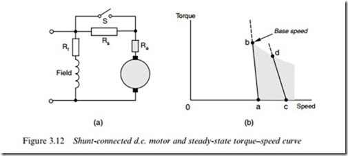
A basic shunt-connected motor has its armature and Weld in parallel across a single d.c. supply, as shown in Figure 3.12(a). Normally, the voltage will be constant and at the rated value for the motor, in which case the steady-state torque/speed curve will be similar to that of a separately excited motor at rated Weld Flux, i.e. the speed will drop slightly with load, as shown by the line ab in Figure 3.12(b). Over the normal operating region the torque–speed characteristic is similar to that of the induction motor (see Chapter 6), so shunt motors are suited to the same duties, i.e. what are usually referred to as ‘constant speed’ applications.
Except for small motors (say less than about 1 kW), it will be neces- sary to provide an external ‘starting resistance’ (Rs in Figure 3.12) in series with the armature, to limit the heavy current which would flow if
the motor was simply switched directly onto the supply. This starting resistance is progressively reduced as the motor picks up speed, the current falling as the back e.m.f. rises from its initial value of zero. In a manual starter the resistance is controlled by the operator, while in an automatic starter the motor armature voltage or current are sensed and the resistance is shorted out in predetermined stages.
We should ask what happens if the supply voltage varies for any reason, and as usual the easiest thing to look at is the case where the motor is running light, in which case the back e.m.f. will almost equal the supply voltage. If we reduce the supply voltage, intuition might lead us to anticipate a fall in speed, but in fact two contrary eVects occur which leave the speed almost unchanged.
If the voltage is halved, for example, both the Weld current and the armature voltage will be halved, and if the magnetic circuit is not saturated the Flux will also halve. The new steady value of back e.m.f. will have to be half its original value, but since we now have only half as much Flux, the speed will be the same. The maximum output power will of course be reduced, since at full load (i.e. full current) the power available is proportional to the armature voltage. Of course if the magnetic circuit is saturated, a modest reduction in applied voltage may cause very little drop in Flux, in which case the speed will fall in proportion to the drop in voltage. We can see from this discussion why, broadly speaking, the shunt motor is not suitable for operation below base speed.
Some measure of speed control is possible by weakening the Weld (by means of the resistance (Rf ) in series with the Weld winding), and this allows the speed to be raised above base value, but only at the expense of torque. A typical torque–speed characteristic in the Weld-weakening region is shown by the line cd in Figure 3.12(b).
Reverse rotation is achieved by reversing the connections to either the Weld or the armature. The Weld is usually preferred since the current rating of the switch or contactor will be lower than for the armature.
Series motor – steady-state operating characteristics
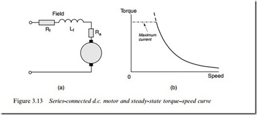
The series connection of armature and Weld windings (Figure 3.13(a)) means that the Weld Flux is directly proportional to the armature current, and the torque is therefore proportional to the square of the current. Reversing the direction of the applied voltage (and hence current) therefore leaves the direction of torque unchanged. This unusual prop- erty is put to good use in the universal motor, but is a handicap when negative (braking) torque is required, since either the Weld or armature connections must then be reversed.
If the armature and Weld resistance volt-drops are neglected, and the applied voltage (V) is constant, the current varies inversely with the speed, hence the torque (T) and speed (n) are related by
A typical torque–speed characteristic is shown in Figure 3.13(b). The torque at zero speed is not inWnite of course, because of the eVects of saturation and resistance, both of which are ignored in equation (3.14).
It is important to note that under normal running conditions the volt- drop across the series Weld is only a small part of the applied voltage, most of the voltage being across the armature, in opposition to the back This is of course what we need to obtain an eYcient energy-conversion. Under starting conditions, however, the back e.m.f. is
zero, and if the full voltage was applied the current would be excessive, being limited only by the armature and Weld resistances. Hence for all but small motors a starting resistance is required to limit the current to a safe value.
Returning to Figure 3.13(b), we note that the series motor deifiers from most other motors in having no clearly deWned no-load speed, i.e. no speed (other than inWnity) at which the torque produced by the motor falls to zero. This means that when running light, the speed of the motor depends on the windage and friction torques, equilibrium being reached when the motor torque equals the total mechanical resisting torque. In large motors, the windage and friction torque is often relatively small, and the no-load speed is then too high for mechanical safety. Large series motors should therefore never be run uncoupled from their loads. As with shunt motors, the connections to either the Weld or armature must be reversed in order to reverse the direction of rotation.
Large series motors have traditionally been used for traction. Often, books say this is because the series motor has a high starting torque, which is necessary to provide acceleration to the vehicle from rest. In fact any d.c. motor of the same frame size will give the same starting torque, there being nothing special about the series motor in this respect. The real reason for its widespread use is that under the simplest possible supply arrangement (i.e. constant voltage) the overall shape of the torque–speed curve Wts well with what is needed in traction applications. This was particularly important in the days when it was simply not feasible to provide any control of the armature voltage.
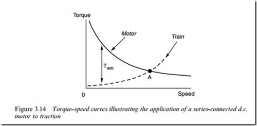
The inherent suitability of the series motor for traction is illustrated by the curves in Figure 3.14, which relate to a railway application. The solid line represents the motor characteristic, while the dotted line is the
steady-state torque–speed curve for the train, i.e. the torque which the motor must provide to overcome the rolling resistance and keep the train running at each speed.
At low speeds the rolling resistance is low, the motor torque is much higher, and therefore the nett torque (Tacc) is large and the train accel- erates at a high rate. As the speed rises, the nett torque diminishes and the acceleration tapers oV until the steady speed is reached at point A in Figure 3.14.
Some form of speed control is obviously necessary in the example above if the speed of the train is not to vary when it encounters a gradient, which will result in the rolling resistance curve shifting up or down. There are basically three methods which can be used to vary the torque–speed characteristics, and they can be combined in various ways.
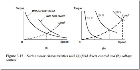
Firstly, resistors can be placed in parallel with the Weld or armature, so that a speciWed fraction of the current bypasses one or the other. Field ‘divert’ resistors are usually preferred since their power rating is lower than armature divert resistors. For example, if a resistor with the same resistance as the Weld winding is switched in parallel with it, half of the armature current will now flow through the resistor and half will flow through the Weld. At a given speed and applied voltage, the armature current will increase substantially, so the Flux will not fall as much as might be expected, and the torque will rise, as shown in Figure 3.15(a). This method is ineYcient because power is wasted in the resistors, but is simple and cheap to implement. A more eYcient method is to provide ‘tappings’ on the Weld winding, which allow the number of turns to be varied, but of course this can only be done if the motor has the tappings brought out.
Secondly, if a multicell battery is used to supply the motor, the cells may be switched progressively from parallel to series to give a range of
discrete steps of motor voltage, and hence a series of torque–speed curves. Road vehicles with 12 V lead–acid batteries often use this ap- proach to provide say 12, 24, and 36 V for the motor, thereby giving three discrete ‘speed’ settings, as shown in Figure 3.15(b).
Finally, where several motors are used (e.g. in a multiple-unit railway train) and the supply voltage is Wxed, the motors themselves can be switched in various series/parallel groupings to vary the voltage applied to each.
Universal motors
In terms of numbers the main application area for the series commutator motor is in portable power tools, foodmixers, vacuum cleaners etc., where paradoxically the supply is a.c. rather than d.c. Such motors are often referred to as ‘universal’ motors because they can run from either a d.c. or an a.c. supply.
At Wrst sight the fact that a d.c. machine will work on a.c. is hard to believe. But when we recall that in a series motor the Weld Flux is set up by the current which also flows in the armature, it can be seen that reversal of the current will be accompanied by reversal of the direction of the magnetic Flux, thereby ensuring that the torque remains positive. When the motor is connected to a 50 Hz supply for example, the (sinusoidal) current will change direction every 10 msec, and there will be a peak in the torque 100 times per second. But the torque will always remain unidirectional, and the speed fluctuations will not be noticeable because of the smoothing eVect of the armature inertia.
Series motors for use on a.c. supplies are always designed with fully laminated construction (to limit eddy current losses produced by the pulsating Flux in the magnetic circuit), and are intended to run at high speeds, say 8–12 000 rev/min. at rated voltage. Commutation and spark- ing are worse than when operating from d.c., and output powers are seldom greater than 1 kW. The advantage of high speed in terms of power output per unit volume was emphasised in Chapter 1, and the universal motor is perhaps the best everyday example which demon- strates how a high power can be obtained with small size by designing for a high speed.
Until recently the universal motor oVered the only relatively cheap way of reaping the beneWt of high speed from single-phase a.c. supplies. Other small a.c. machines, such as induction motors and synchronous motors, were limited to maximum speeds of 3000 rev/min at 50 Hz (or 3600 rev/min at 60 Hz), and therefore could not compete in terms of power per unit volume. The availability of high-frequency inverters (see Chapter 8) has opened up the prospect of higher speciWc outputs from induction motors, but currently the universal motor remains the dominant force in small low-cost applications, because of the huge investment that has been made over many years to produce them in vast numbers.
Speed control of small universal motors is straightforward using a triac (in eVect a pair of thyristors connected back to back) in series with the a.c. supply. By varying the Wring angle, and hence the proportion of each cycle for which the triac conducts, the voltage applied to the motor can be varied to provide speed control. This approach is widely used for electric drills, fans etc. If torque control is required (as in hand power tools, for example), the current is controlled rather than the voltage, and the speed is determined by the load.
Compound motors
By arranging for some of the Weld MMF to be provided by a series winding and some to be provided by a shunt winding, it is possible to obtain motors with a wide variety of inherent torque–speed characteristics. In practice most compound motors have the bulk of the Weld MMF provided by a shunt Weld winding, so that they behave more or less like a shunt connected motor. The series winding MMF is relatively small, and is used to allow the torque–speed curve to be trimmed to meet a particular load requirement.
When the series Weld is connected so that its MMF reinforces the shunt Weld MMF, the motor is said to be ‘cumulatively compounded’. As the load on the motor increases, the increased armature current in the series Weld causes the Flux to rise, thereby increasing the torque per ampere but at the same time, resulting in a bigger drop in speed as compared with a simple shunt motor. On the other hand, if the series Weld winding opposes the shunt winding, the motor is said to be ‘diVerentially compounded’. In this case an increase in current results in a weakening of the Flux, a reduction in the torque per ampere, but a smaller drop in speed than in a simple shunt motor. DiVerential com- pounding can therefore be used where it is important to maintain as near constant-speed as possible.
