FOUR-QUADRANT OPERATION AND REGENERATIVE BRAKING
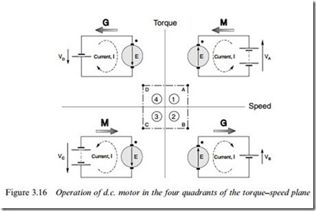
As we saw in Section 3.4, the beauty of the separately excited d.c. motor is the ease with which it can be controlled. Firstly, the steady-state speed is determined by the applied voltage, so we can make the motor run at any desired speed in either direction simply by applying the appropriate magnitude and polarity of the armature voltage. Secondly, the torque is directly proportional to the armature current, which in turn depends on the diVerence between the applied voltage V and the back e.m.f. E. We can therefore make the machine develop positive (motoring) or negative (generating) torque simply by controlling the extent to which the applied voltage is greater or less than the back e.m.f. An armature voltage controlled d.c. machine is therefore inherently capable of what is known as ‘four-quadrant’ operation, with reference to the numbered quadrants of the torque–speed plane shown in Figure 3.16.
Figure 3.16 looks straightforward but experience shows that to draw the diagram correctly calls for a clear head, so it is worth spelling out the key points in detail. A proper understanding of this diagram is invaluable as an aid to seeing how controlled-speed drives operate.
Firstly, one of the motor terminals is shown with a dot, and in all four quadrants the dot is uppermost. The purpose of this convention is to indicate the sign of the torque: if current flows into the dot, the machine produces positive torque, and if current flows out of the dot, the torque is negative.
Secondly, the supply voltage is shown by the old-fashioned battery symbol, as use of the more modern circle symbol for a voltage source would make it more diYcult to differentiate between the source and the circle representing the machine armature. The relative magnitudes of applied voltage and motional e.m.f. are emphasised by the use of two battery cells when V > E and one when V < E.
We have seen that in a d.c. machine speed is determined by applied voltage and torque is determined by current. Hence on the right-hand side of the diagram the supply voltage is positive (upwards), while on the left-hand side the supply voltage is negative (downwards). And in the upper half of the diagram current is positive (into the dot), while in the lower half it is negative (out of the dot). For the sake of convenience, each of the four operating conditions (A, B, C, D) have the same magnitude of speed and the same magnitude of torque: these translate to equal magnitudes of motional e.m.f. and current for each condition.
When the machine is operating as a motor and running in the forward direction, it is operating in quadrant 1. The applied voltage VA is positive and greater than the back e.m.f. E, and positive current there- fore flows into the motor: in Figure 3.16, the arrow representing VA has accordingly been drawn larger than E. The power drawn from the supply (VAI ) is positive in this quadrant, as shown by the shaded arrow labelled M to represent motoring. The power converted to mechanical form is given by EI, and an amount I 2R is lost as heat in the armature. If E is much greater than IR (which is true in all but small motors), most of the input power is converted to mechanical power, i.e. the conversion process is eYcient.
If, with the motor running at position A, we suddenly reduce the supply voltage to a value VB which is less than the back e.m.f., the current (and hence torque) will reverse direction, shifting the operating point to B in Figure 3.16. There can be no sudden change in speed, so the e.m.f. will remain the same. If the new voltage is chosen so that E – VB ¼ VA – E, the new current will have the same amplitude as at position A, so the new (negative) torque will be the same as the original positive torque, as shown in Figure 3.16. But now power is supplied from the machine to the supply, i.e. the machine is acting as a generator, as shown by the shaded arrow.
We should be quite clear that all that was necessary to accomplish this remarkable reversal of power flow was a modest reduction of the voltage applied to the machine. At position A, the applied voltage was E þ IR, while at position B it is E– IR. Since IR will be small compared with E, the change (2IR) is also small.
Needless to say the motor will not remain at point B if left to its own devices. The combined eVect of the load torque and the negative ma- chine torque will cause the speed to fall, so that the back e.m.f. again falls below the applied voltage VB, the current and torque become positive again, and the motor settles back into quadrant 1, at a lower speed corresponding to the new (lower) supply voltage. During the deceleration phase, kinetic energy from the motor and load inertias is returned to the supply. This is therefore an example of regenerative braking, and it occurs naturally every time we reduce the voltage in order to lower the speed.
If we want to operate continuously at position B, the machine will have to be driven by a mechanical source. We have seen above that the natural tendency of the machine is to run at a lower speed than that corresponding to point B, so we must force it to run faster, and create an e.m.f greater than VB, if we wish it to generate continuously.
It should be obvious that similar arguments to those set out above apply when the motor is running in reverse (i.e. V is negative). Motoring then takes place in quadrant 3 (point C), with brief excursions into quadrant 4 (point D, accompanied by regenerative braking), whenever the voltage is reduced in order to lower the speed.
Full speed regenerative reversal
To illustrate more fully how the voltage has to be varied during sus- tained regenerative braking, we can consider how to change the speed of an unloaded motor from full speed in one direction to full speed in the other, in the shortest possible time.
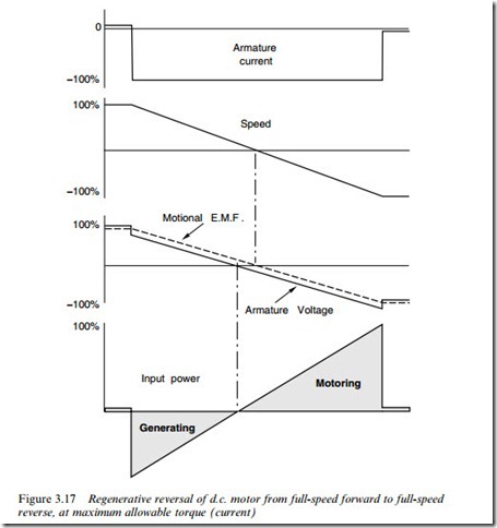
At full forward speed the applied armature voltage is taken to be þV (shown as 100% in Figure 3.17), and since the motor is unloaded the no- load current will be very small and the back e.m.f. will be almost equal to V. Ultimately, we will clearly need an armature voltage of -V to make the motor run at full speed in reverse. But we cannot simply reverse the applied voltage: if we did, the armature current immediately afterwards would be given by ( – V – E)=R, which would be disas- trously high. (The motor might tolerate it for the short period for which it would last, but the supply certainly would not!).
What we need to do is adjust the voltage so that the current is always limited to rated value, and in the right direction. Since we want to decelerate as fast as possible, we must aim to keep the current negative, and at rated value (i.e. -100%) throughout the period of deceleration and for the run up to full speed in reverse. This will give us constant torque throughout, so the deceleration (and subsequent acceleration) will be constant, and the speed will change at a uniform rate, as shown in Figure 3.17.
We note that to begin with, the applied voltage has to be reduced to less than the back e.m.f., and then ramped down linearly with time so that the diVerence between V and E is kept constant, thereby keeping the current constant at its rated value. During the reverse run-up, V has to be numerically greater than E, as shown in Figure 3.17. (The diVer-
ence between V and E has been exaggerated in Figure 3.17 for clarity: in a large motor, the diVerence may only be one or two percent at full speed.)
The power to and from the supply is shown in the bottom plot in Figure 3.17, the energy being represented by the shaded areas. During the deceleration period most of the kinetic energy of the motor (lower shaded area) is progressively returned to the supply, the motor acting as a generator for the whole of this time. The total energy recovered in this way can be appreciable in the case of a large drive such as a steel rolling mill. A similar quantity of energy (upper shaded area) is supplied and stored as kinetic energy as the motor picks up speed in the reverse sense.
Three Wnal points need to be emphasised. Firstly, we have assumed throughout the discussion that the supply can provide positive or nega- tive voltages, and can accept positive or negative currents. A note of caution is therefore appropriate, because many simple power electronic converters do not have this flexibility. Users need to be aware that if full four-quadrant operation (or even two-quadrant regeneration) is called for, a basic converter will probably not be adequate. This point is taken up again in Chapter 4. Secondly, we should not run away with the idea that in order to carry out the reversal in Figure 3.17 we would have to work out in advance how to proWle the applied voltage as a function of time. Our drive system will normally have the facility for automatically operating the motor in constant-current mode, and all we will have to do is to set the new target speed. This is also taken up in Chapter 4. And Wnally, we must remember that the discussion above relates to separately excited motors. If regenerative braking is required for a series motor, the connections to either the Weld or armature must be reversed in order to reverse the direction of torque.
Dynamic braking
A simpler and cheaper but less eVective method of braking can be achieved by dissipating the kinetic energy of the motor and load in a resistor, rather than returning it to the supply. A version of this tech- nique is employed in the cheaper power electronic converter drives, which have no facility for returning power to the mains.
When the motor is to be stopped, the supply to the armature is removed and a resistor is switched across the armature brushes. The motor e.m.f. drives a (negative) current through the resistor, and the negative torque results in deceleration. As the speed falls, so does the e.m.f., the current, and the braking torque. At low speeds the braking torque is therefore very small. Ultimately, all the kinetic energy is converted to heat in the motor’s own armature resistance and external resistance. Very rapid initial braking is obtained by using a low resistance (or even simply short-circuiting the armature). Dynamic braking is still widely used in traction because of its simplicity, though most new rapid transit schemes employ the more energy-eYcient regenerative braking process.

