Thermal devices are used on all types of motors. Single- and dual-voltage capacitor-start motor connections with thermal devices are discussed here.
Single-Voltage Capacitor-Start Motor
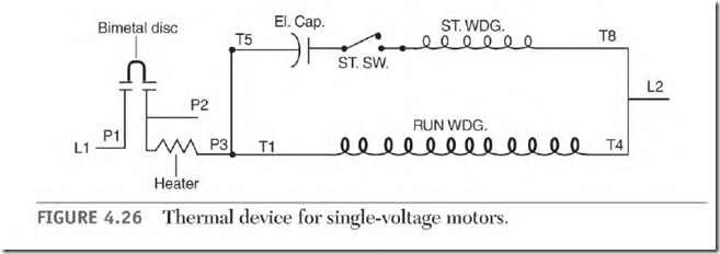
Figure 4.26 shows a thermal device connected to a single-voltage capacitorstart motor. Line I is connected to Pl. P3 is connected directly to the run winding. A lead marked Tl is connected to P3, making it accessible to combine start-winding leads T5 or T8 with T 1. (To reverse the motor, interchange T5 and T8.) T4 and T5 or T8 are connected to L2.
PI (line l) is disconnected from all circuits when the thermal device functions because of an overload.
If the thermal device becomes defective, Tl (with T5 or T8) can be connected directly to line 1. This will bypass the defective thermal device. (The heat element would melt if Tl were inadvertently connected to line 2 when PI is connected to line 1.)
The start winding is sometimes connected to P2 so that its amperes don’t affect the heat element. It could be destroyed at this location if the heat element becomes open.
Dual-Voltage Motor, Connected Low Voltage
The dual-voltage motor’s run winding has two circuits. Each circuit contains exactly half of the run winding. This makes it possible to connect the run winding high voltage (series) or low voltage (parallel).
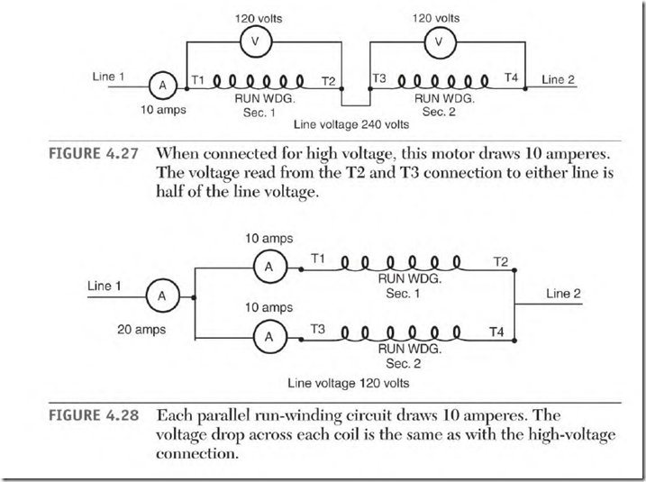
Figure 4.27 shows the voltage value across each pole when the winding is connected high voltage (series). Figure 4.28 shows the same voltage value across each pole when the winding is connected low voltage (parallel). When
the voltage is the same across each pole, the amperes through each pole are the same (for both connections).
Full-load amperes for this motor are 20 amps (low voltage) and 10 amps (high voltage). When connected low voltage (parallel), each circuit draws 10 amps, for a total of 20 amps. When connected high voltage, the run circuit draws 10 amps.
The heat element of the thermal device is connected in series with one circuit of the run winding. Whether connected high or low voltage, the fullload amperes through the heat element will be 10 amps. The trip value for this motor’s protective device is based on a 10-amp load.
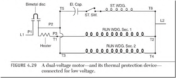
Figure 4.29 shows a dual-voltage capacitor-start motor connected low voltage. Line 2 is connected to T2, T4, and T5 (or T8). (To reverse this motor, interchange T5 and T8.) Line 1 is connected to Pl. Tl (from the run winding) and an external lead labeled Tl are internally connected to terminal P3 of the thermal device.
External lead Tl is sometimes connected to T5 (or T8) and insulated. Some motor nameplates specify that T5 (or T8) be connected to P2. (The startwinding current won’t go through the heat element when connected to P2.)
Run-winding lead T3 is connected to P2 and insulated. The current of T3 (10 amps) will bypass the heat element when connected to P2. If the thermal device opens because of an overload, Tl and T5 (or T8) are disconnected from line 1. At the same time, P2 disconnects T3 from line 1. T2 T4, and T5 (or T8) remain connected to line 2.
Dual-Voltage Motor, Connected High Voltage
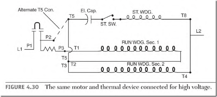
Figure 4.30 is the same motor as described above, but connected for high voltage. At full load, the run winding draws 10 amperes. Line I is connected
to Pl. P2 isn’t used and is insulated, and T2, T3, and T5 (or T8) are joined and insulated. T4 and T5 (or T8) are connected to line 2. (T5 or T8 can also be connected to P2.) This motor can be reversed by interchanging T5 and T8.
Whether this motor is connected high or low voltage, each run winding pole must have 10 amps flowing through it to produce full power.


