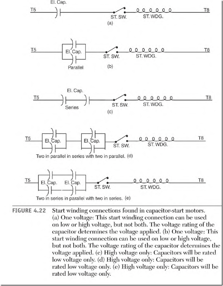
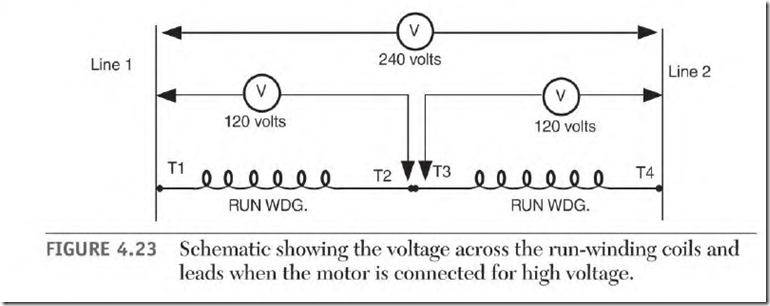
Figure 4.22 (a through e) covers most capacitor-start motor connections. There is no standard order of sequence for the components. Regardless of the sequence, the start switch contacts must shut off the electrolytic capacitor(s) and the start winding. Figures 4.22 (a) and (b) can be used on high-voltage, low-voltage, or dual-voltage applications. The capacitor’s voltage rating must be the same as the applied voltage when the application is a single voltage. Dual-voltage applications require lower-voltage capacitors. The run winding is used as an autotransformer to keep the voltage applied to the start winding low. Figure 4.23
shows the voltage value when the dual-voltage run winding is connected for high voltage. When the start winding is connected across one-half of the run winding, it will receive only half of the applied voltage.
The series connections in Figs. 4.22 (c) through (e) are all high-voltage applications. The capacitors are all rated low voltage. Figures 4.22 (d) and (e) are connections used on larger-horsepower motors.

