When one line of a three-phase power supply opens, the power becomes single phase. If this happens while the motor is running, its power output is cut approximately in half. It will continue to run, but it can no longer start by itself. Like a single-phase motor without its start winding energized, it has no rotating magnetic field to get it started.
Single-Phase Damage to a Wye-Connected Nine-Lead Motor
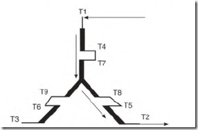
Figure 6.34 shows the current path through the wye connection. Thro phases of the windings are energized; the third phase has no current flow. If the motor’s protection device doesn’t function, the two phases that carry
FIGURE 6.34 Schematic showing where the current flows in a Mye-connected motor with line 3 open (single phase).
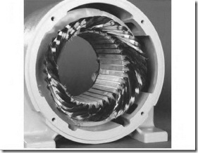
current will overheat and char. The phase without current flow will look normal. Figure 6.35 is a picture of a single-phase-caused burnout in a four-pole winding.
FIGURE 6.35 A wye-connected motor that failed because of a single-phase condition. Line 3 is open. EASA.
Single-Phase Damage to a Delta-Connected Nine-Lead Motor
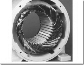
Figure 6.36 shows the current path through the delta connection, with an open phase. The A phase has extremely high current flowing through it. The other two phases have about half as much. The phase with high current will overheat and char if the motor’s protection device doesn’t disconnect it. The phases that carry less current will look normal. Figure 6.37 is a picture of a single-phase-caused burnout in a four-pole winding.
Submerged Motor
If a three-phase motor has been submerged in water but not energized, there’s a good chance it won’t need rewinding or replacing. Cleaning and baking the windings may be all that’s needed.
The motor should be disassembled as soon as possible. If the motor has ball bearings, they should be replaced. If it has sleeve bearings, the oil wicking material will pit or rust the shaft area located in the bearing window. Replace the oil wick material immediately. If the motor has an oil reservoir and oil ring, the reservoir should be thoroughly cleaned.
The windings should be first tested with an ohmmeter. (A wet winding should never be subjected to a test voltage that could arc through the wet slot insulation.) The baking temperature shouldn’t exceed 200 F. The ohmmeter test should read infinity after baking. After the windings have been cleaned, dried, and tested, they will need a coat of air-drying varnish.
When water soaks the slot insulation, the copper windings and the core become a form of battery. A small voltage can be read (with a millivoltmeter)
FIGURE 6.36 Schematic showing where the current flows in a delta-connected motor with line 3 open (single phase).
FIGURE 6.36 Schematic showing where the current flows in a delta-connected motor with line 3 open (single phase).
6
FIGURE 6.37 A delta-connected motor that failed because of a single-phase condition. Line 3 is open. EASA.
between the winding and the frame when the slot insulation is wet. A zero reading indicates the motor has been baked long enough.
A megohmmeter, hi-pot, or surge tester can be used when an ohmmeter test shows infinity.
Assorted Rotor Problems
This is a review of the rotor problems found in Chapter 3, with more detailed information:
Open Rotor Bars
Open rotor bars or end rings usually necessitate replacing the motor. They can be repaired, recast, or rebarred (if it’s economical). (It’s important that any replaced metal be the same as the original.)
Open rotor bars are caused by overload burnout, arcing in the slot from a shorted winding, loose bar vibration, thermal growth stress (from starting), flaws in bar material (casting flaw), and poor connections with end rings.
Open rotor bars cause loss of power. If too many rotor bars are open, a loaded motor will draw amperes high enough to open its protection device. With no load, the amperes will be very low. Slow starting and lower-thanrated RPM are a sign of broken rotor bars.
Open End Rings
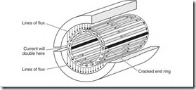
Open end rings cause uneven torque and some power loss. A ring with one open spot will soon develop more open spots. Each time the open spot crosses a 90 0 spot between poles, the current will double in the ring area between the next two poles (Fig. 6.38).
![]() Causes of open end rings and/or cracked end rings include flawed casting; motor burned out from overload; motor redesigned for a higher speed (without increased size of end ring); ring material drilled away for balancing; thermal growth stress; and mechanical damage.
Causes of open end rings and/or cracked end rings include flawed casting; motor burned out from overload; motor redesigned for a higher speed (without increased size of end ring); ring material drilled away for balancing; thermal growth stress; and mechanical damage.
A bubble or void in an end ring can cause an electrical vibration. (This type of vibration can’t be corrected by balancing.) It can be detected by cutting the power and allowing the motor to coast. Electrically caused vibrations will always cease as soon as the power is shut off.
FIGURE 6.38 Current flow in a squirrel cage rotor with an open end ring.
Misaligned Rotor/Stator Iron
A motor with a misaligned rotor will draw high amperes and will lose power. The magnetic path becomes distorted, causing the magnetizing amperes to increase. The stator windings will char and resemble an overload burnout. Possible causes of a misaligned rotor include:
![]() Bearings not installed correctly on the shaft (extended race on wrong side)
Bearings not installed correctly on the shaft (extended race on wrong side)
![]() Captive bearing not held as originally placed
Captive bearing not held as originally placed
![]() Stator core shifted on its shell
Stator core shifted on its shell
![]() A rotor replaced with a shorter rotor. A rotor with the same diameter but longer than the original will work, but some efficiency is lost.
A rotor replaced with a shorter rotor. A rotor with the same diameter but longer than the original will work, but some efficiency is lost.
Rotor Dragging on the Stator
If the rotor drags on the stator and the bearings aren’t worn, it’s common practice to “skim” the rotor on a lathe. The process increases the air gap, which increases the no-load amperes. The increased amperes are similar to a misaligned rotor and stator iron. The magnetic circuit is degraded, so it takes more amperes to magnetize the motor’s iron. The motor will run hotter than normal, because the motor is drawing more magnetizing amperes. If the load is at maximum or there are any adverse conditions (such as low voltage or frequent starts), the motor should be replaced. (There will be some permanent power and efficiency loss.)
Rotor Loose on Shaft
A loose rotor on a shaft makes a rumbling or vibrating sound. The sound will cease after the power is turned off (while the motor is coasting). If the motor has operated this way for very long, a red dust will form between the shaft and rotor iron. This dust is oxidized iron, caused by the rubbing action between the shaft and the rotor iron. (The same thing happens when a pulley or bearing is loose on a shaft.)
The decision to repair a loose rotor depends on the price of a replacement motor and the importance of the motor in the plant operation.
There are options for this problem: The rotor (and shaft) can be replaced;
the rotor can be bored out and a new shaft fitted to it; or a thin metal wedge can be driven between the shaft and rotor to secure it.
Wedging the rotor may offset it enough to make it drag on the stator. It would then be necessary to skim the rotor—on a lathe—to keep it from dragging. The rotor should be bored and fitted with a new shaft. In most cases, it is more economical to replace the motor.
When Motors Overheat
Overheating is a major cause of insulation and bearing failure. Causes of overheating include the following:
• Line
• Operator
• Control
• Motor fault
• Location
• Maintenance
Line-Caused Overheating
There are four causes of line-caused overheating: overvoltage, low voltage, unbalanced voltage, and a high-resistance connection.
Overvoltage
Overvoltage can cause a normally loaded motor to overheat. NEMA standard specifications allow motors a voltage deviation of + 10 percent from their nameplate voltage rating.
All motors will start their load faster when voltage is high. T-frame motors, however, overheat (on overvoltage) more than the older U-frame or high-efficiency motors (even with less than 10 percent overvoltage). T-frame motors have smaller copper wire in their windings and significantly less iron in their core. (They depend on a high volume of air to keep them cool.)
NEMA approved the T-frame motor’s design in 1967. This downsized motor was made possible by the development of insulation that could tolerate higher temperature.
A big improvement in the T-frame design is the use of ball bearings instead of sleeve bearings. Ball bearings make it possible to have a closer fit
6 Troubleshooting
between the rotor and the core, thus reducing the air gap. (Air gap reduces a motor’s efficiency more than other forms of loss.) The induction motor and the transformer have very comparable characteristics—both transform power from one winding to another. Unlike a motor, a transformer has no air gap.
Therefore, some transformers have efficiency ratings above 99 percent.
Earlier T-frame motors had higher efficiency than U-frame motors, as less iron was used in the core and rotor. (Magnetizing more iron than necessary lowers the efficiency.) Design changes that improved the T-frame motor’s efficiency included getting rid of excess iron and reducing the air gap. However, because of the reduced overall size, there was a loss of area for heat dissipation.
Some motor manufacturers reduced material used in the electrical and mechanical components too much. (One manufacturer made fractionalhorsepower motors that were too fragile to ship. The stator core was mounted in a very thin steel shell. Several dents were punched in the shell to hold it in place. The core was easily dislodged with only moderately rough handling.)
Manufacturers increased the size of the motor’s cooling fan and installed metal baffles to direct the air on the windings. Air volume was increased because of the extra heat created by undersized wire. (Power used to move the extra air reduces the motor’s efficiency.)
In one case, there were two motors (made by the same manufacturer) that had different horsepower ratings. They had identical core and rotor dimensions and identical electrical data. One motor was rated 1/3 horsepower and the other 1/2 horsepower. The 1 /3-horsepower motor had a totally enclosed frame, and the lh-horsepower motor had an open frame. The nameplate RPM of the lh-horsepower motor was lower than that of the 1/3-horsepower motor. By loading the motor down a few RPM, it produced 1/2 horsepower. Air flowing through the open end brackets increased the amount of cooling capability enough to compensate for the increased amperes and heat.
Low Voltage
Low voltage affects all motors in the same way—they lose power and may take too long to start a load. Prolonged starts cause excess heat in the stator winding (at the start of its duty cycle). Another concern with low voltage is the heat that develops from frequent starting.
Under maximum load, low voltage causes the motor to run more slowly than the nameplate RPM. Technically, it’s overloaded. It will run hot and will soon fail.


![clip_image002[5] clip_image002[5]](http://machineryequipmentonline.com/electric-equipment/wp-content/uploads/2017/04/clip_image0025_thumb4.jpg)

