Buffer
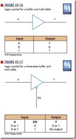
A buffer is a special logic gate that isolates conventional gates from other circuitry and provides a high driving current for heavy circuit loads or fan- out. Fan-out refers to the number of input gates connected to a single logic gate output. Buffers pro- vide noninverting input and output. A 1 in provides a 1 out and a 0 in provides a 0 out. Figure 42-16 shows the schematic symbol for a basic buffer with its truth table.
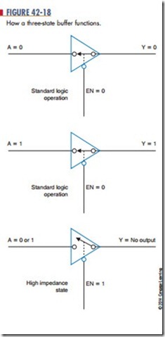
Another type of buffer is the three-state buffer shown with its truth table in Figure 42-17. The three- state buffer has the usual 1 and 0 output states but it also has a third state, which is referred to as a high- impedance state. This state provides an open circuit between the input circuitry and the output and is controlled by the EN line. The EN line represents an enable/disable control input. Figure 42-18 shows how the three-state buffer operates.
Questions
1. How does a buffer differ from an inverter?
EN 2. What function does a buffer serve?
3. Draw the symbols for a buffer and a three-state
buffer.
4. Develop a truth table for a three-state buffer.
5. What conditions must exist for no output from a three-state buffer?

