DISC RECORDING AND REPRODUCTION
When Edision first developed phonograph recording, he used vertical motions of the recording stylus to record sound vibrations. This came to be known as the ‘hill and dale’ method of recording. However, the ‘hills’ in the record groove had to lift the playback arm and cartridge. Since early arms and cartridges were relatively heavy, this motion caused excessive wear and tear. The record industry, therefore, adopted the lateral recording method, in which the needle moves from side to side in accordance with the sound vibrations. All commercial monophonic records for home use are laterally recorded, and monophonic pickups are designed accordingly. The year 1946 marks the start of the disc hi-fi. The binaural record and a special tonearm with which to play it appeared in 1952. In 1957, first stereo-disc was demonstrated and the moving-magnet stereo pickup was invented.
MAKING THE TAPE
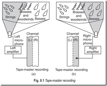
The live performance is recorded on tape, Fig. 8.1. Often, each instrument and a singer is given a separate microphone and a separate channel. Professional tape recordings may have as many as 32 channels so that the sound of each instrument can be individually monitored – balanced, adjusted, and enhanced. Different channels can be recorded at different times.
The placement of microphone is very important and the optimum position are decided with experience.
The multiple channels recorded in the studio are mixed down to stereo before the record is cut. At the mixing stage, record producers make many decisions that determine the end sound quality of a performance.
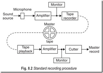
In the standard recording procedure Fig. 8.2, the microphones feed the signals to preamplifiers. From there the signals go to amplifiers, then to a tape recorder. In recent innovations with noise reduction systems the process is much more complex but offers greater reduction of noise.
The tapes run at speeds of 15 or 30 inches per second (ips) to ensure high quality and accurate response.
MAKING THE RECORD
When the master tape is played, its magnetic patterns are converted into electrical signals. These are fed through amplifiers to a cutter head on a lathe which converts these signals into mechanical motion and causes a cutting stylus to move as dictated by the signals on the tape. Thus, an incredibly complex groove is inscribed into a master disc. Moulds are then made from which the records are stamped.
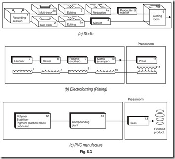
PROFESSIONAL RECORD MANUFACTURE (FIG. 8.3)
1. The recording session may be in a studio or an external location. A simple two-microphone balance may be used, or a multi-microphone set-up.
2. Multi-mix as well as two-mix sessions can be recorded directly onto twin-track 1/4 in tapes.
2a. Multi-mix sessions are more commonly recorded on multi-track machines (1 or 2 in tape : 8, 16, 24 or 32 tracks).
3. and 3a. The best takes are edited together to produce a complete performance.
4. An edited twin-track tape is called a master and will usually be copied for safety.
4a. A multi-track tape is copied via a mixing desk by a process known as reduction, to make …
5. …..twin-track production master.
6. The twin-track tape goes to the cutting room for transfer to lacquer.
7. The lacquer is sprayed with silver to make it conductive.
8. It is put into an electroplating bath and a nickel master is grown onto the silver coating. The lacquer is discarded leaving the master which is now a mirror image of the master.
9. By a further plating operation a positive (or mother) is grown. The master can be re-used.
10. From the positive a matrix (or stamper) is grown and this has protruding grooves like the master.
11. A pair of stampers goes to the press to make a record.
12. The main constituents of the vinyl are a vinyl copolymer, a stabiliser, a lubricant and a pigment.
The latter is usually carbon black, to produce the traditional record colouring.
13. The materials are compounded and fed to the press by extrusion or as cakes of small dice-like particles; from these the final product is pressed.
14. Manual semi-automatic and fully-automatic presses are all used in record manufacture today.
STEREO PICKUP TECHNIQUES
The most general type of stereo pickup technique is called time-intensity pickup. This means that the signals in the two stereo channels will vary in both intensity and time according to the difference in direction and in distance of the sound source from the two microphones.
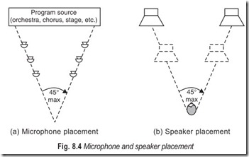
The stereo effect can be obtained by picking up the sound with two microphones spaced a certain distance apart and located in front of the sound source. If they are too close the stereo effect is lost. Experiments have led to the conclusion that there is a definite optimum relation between the microphones separation and their distance from the source. A similar relation exists between the listeners’ speakers and their distance from him. This is illustrated in Fig. 8.4. In practice the angle at the listener should not be less than 30 degrees nor exceed 45 degrees. This relation keeps the distance of the listener from the speakers approximately the same as the distance between the speakers and ensures sufficient time intensity variation to provide stereo effect.
A good rule to follow is to spread the microphones as far apart as you can and still pickup an appreciable amount of sound from the middle portion of the source. Usually the pattern will be such that they can be placed along the sides of a triangle (see Fig. 8.4).
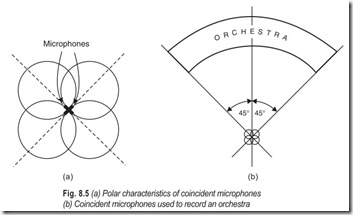
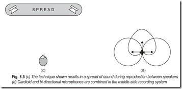
Yet another method, referred as intensity-difference system, is sometimes used in stereo recording. In this system, the microphones are not spaced; however, they have a directional characteristic as shown in Fig.8.5. The stereo effect is obtained by proper orientation of the microphones. One method is to mount the microphones at 90 degrees to each other and 45 degrees to the centre of the source.
STEREO RECORDING SYSTEMS
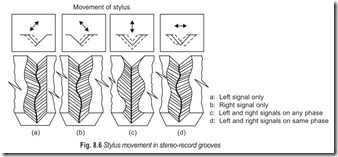
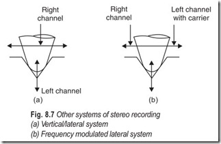
Stereo records can be produced in two ways. In one method, one track is cut in the record groove by the side- to-side (lateral) movement of the record cutter, as in cutting a mono-record. The second track is cut simultaneously in the same groove but with an up-and-down (hill-and-dale) movement. This is shown in Fig8.6 and 8.7. The cartridge in the record player must then be able to follow both the lateral and hill-and-dale movements.
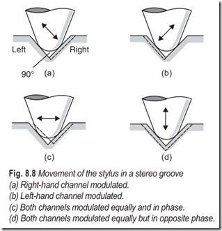
In the second method, the groove is a V-shaped with a 90° angle between sides, as shown in Fig. 8.8. Both tracks are cut by a quasilateral method, one track on each side of the V. The two tracks are, therefore, 90° apart and require a cartridge that can follow both tracks at once.The second method, known as the 45°– 45° system, is the one used for modern stereo recordings. The principles used in cutting grooves in this process are similar to both the older monophonic lateral and hill-and-dale methods. However, there is one important difference. In modern stereo recording a single stylus (cutter) simultaneously cuts an independent information channel into each wall of the record groove.
EXTRACTING THE MUSIC
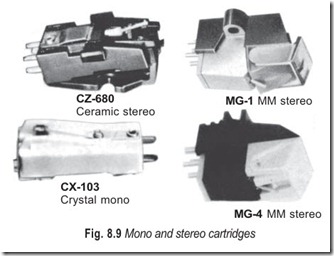
There is only one way to extract the music and that is with a cartridge. A cartridge (Fig. 8.9) consists of three basic elements : the stylus, the cantilever, and the generating system.
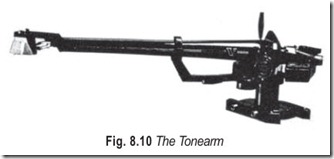
1. The stylus : The stylus is the only part which makes contact with the record. A force must be exerted by the tonearm Fig. 8.10, to keep the stylus in the centre of the groove when the record is spinning.
This tracking weight is usually low—between one and two grams—but because the stylus makes contact with less than one millionth of a square inch of the record surface it exerts tremendous pressure : 6000 pounds per square inch. With such enormous pressure any roughness or irregularity in the stylus will cause record damage. The stylus must also be hard or it will wear out quickly. For these reasons, high-quality styluses are made from the hardest material known to man—diamond.
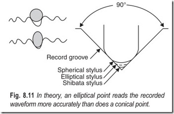
There are three common shapes of styluses, Fig 8.11; spherical stylus, elliptical stylus, and fine-line or line-cut stylus.
(i) Spherical Stylus: The spherical (also called conical) shape is the least expensive to manufacture and is used in low cost cartridges. Unfortunately, this stylus cannot accurately trace the highest musical tones.
(ii) Elliptical Stylus : The more expensive elliptical stylus has a narrow profile enabling it to follow the complex undulations of the groove with greater precision. It is used in the majority of high quality cartridges.
(iii) Fine-Line Stylus : A third stylus shape, which goes under various names such as fine-line and line cut, provides more faithful tracking of the groove. It has an even narrower profile than the elliptical shape and makes contact with a wider area of the groove, thus reducing the tremendous pressure the stylus exerts on the delicate record surface. This shape also reduces record wear.
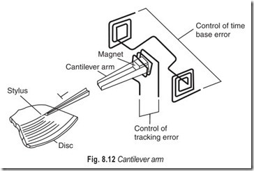
2. The Cantilever : The precious diamond moves at tremendous speed through the complex groove of a spinning record. A delicate armature, called the cantilever, transmits its motions to the generating system, (see Fig. 8.12).
In order for the cantilever to relay the minute movements of the stylus, it should be light weight so it can respond rapidly to the twists and turns of the record groove. And it must be rigid because any bending or flexing adds distortion and sound colouration. Obviously, light weight and high strength require great ingenuity in design and materials.
3. The Generating System : High fidelity cartridges are based on the law of physics which states : when a material capable of conducting electricity is set into motion in a magnetic field—or when a magnet is near a conductive material (such as copper coils)—electrical signals are generated. The direction and speed of the movement determines the ultimate strength of the generated signal.
Thus the generating system of a cartridge converts the movement of the stylus and cantilever into what is termed the output signal. There are three ways of doing this : moving the magnet, moving the iron and moving the coil.
TYPES OF MICROGROOVES
A mono-microgroove is formed on the disc—a lacquer blank the first stage in the manufacturing process by a cutter which moves laterally (side-to-side) only. This is shown in Fig 8.13 through 8.16.
The reproducing stylus will move from side-to-side when tracing the modulated groove, as indicated in Fig. 8.14, and it is easy to visualise that this is the only movement required for the reproduction of a single channel of information.
The depth of the groove does not change. It is of course, usual to speak of grooves, although there is only one continuous spiral. On microgroove discs there are 150–300 grooves to the inch.
In stereo recording, an unmodulated groove would be essentially the same as that on a mono disc. It is, however, required to accommodate two separate channels of information and to arrange for these to be traced by one stylus. Therefore, a signal is cut on each groove wall: one signal is geometrically at 90 degrees to the other but at 45 degrees to the surface of the disc. In a recording of any complex sound, the stylus follows a variety of slanting, vertical and lateral movements which depend on the relative amplitudes and phase of the signals.
Whereas a stylus of 0.001 inch tip radius is used to trace mono discs, a smaller tip is used for the more complex stereo groove. The correct size for most high fidelity applications is 0.0005 inch and it is advisable to use this size for all pickups provided that the playing weight is suitably low. Since the tip radius is half that for mono, the tip area is also smaller by a factor of two. This means that the pressure on the stereo groove is about twice that on the mono groove, and stereo pickups must therefore track at a smaller weight.
Primitive 12 inch discs with 78 rpm speed could give a playing time of 3 minutes only. This was too short a playing time. It was increased to 6 minutes by introducing equalisation. This was still considered to be short. Two factors combine to increase the playing time necessary for continuous playback: the speed of rotation (rpm) and size of the groove.
1. Speed of rotation : To increase the time for continuous playback the speed of rotation was decreased from 78 to 45 rpm for extended play (EP). It was further reduced from 45 to 33 1/3 rpm for long play (LP).
2. Size of the groove : The size of the groove width on top was reduced from 150 µm (6 mil) to 50 µm (2mil). 150 µm grooves were referred to as coarse grooves. The size of stereo grooves was brought down to 6 µm (0.25 mil). Because of their miniscule size stereo grooves are referred to as fine grooves or more appropriately as microgrooves.
|
Maximum number of grooves = R/W |
…(8.1) |
|
|
where |
R = radius of the disc |
|
|
and |
W = width of the groove |
assuming that the grooves on adjacent spirals just touch each other.
Example 8.1 Find the number of grooves per cm on a disc of 300 mm if the groove width is 50 µm.
Solution Radius (R) of the disc = 150 mm = 150 × 10–3 m
Groove width (W ) = 50 µm = 50 × 10–6 m
The actual number of grooves will depend on the spacing between adjacent grooves.
MOVING-MAGNET CARTRIDGES
The most common generating method is to mount a magnet on the back of the cantilever. As the motion of the stylus and cantilever causes the magnet to move, the magnetic properties change in the nearby coils and signals (voltages) corresponding to the mechanical changes are generated.
Moving-magnet cartridges are less costly to manufacture since the coils can be machine-wound. They have high output and when the stylus wears out, simply slide the old stylus assembly out of the body of the cartridge and slide a new one in.
The magnetic pickup is a current-operated device. The construction of magnetic pickups varies greatly. The movable magnet is damped. This is accomplished in a number of ways, depending on the construction of the particular cartridge.
The coil is connected directly to the input of the preamplifier. The frequency range of a magnetic pickup is greater than that of the crystal type. The finest magnetic pickups have a frequency range from 50 to over 15,000 Hz. The distortion content of a fine magnetic pickup may be as low as 0.1 per cent at 400 Hz, and 1 per cent to 4 per cent at high frequencies. A typical moving-magnet cartridge is shown in Fig. 8.17.
MOVING-IRON CARTRIDGES
To improve tracking in the groove and achieve low distortion the mass of the cartridge parts that move the moving mass—must be lowered.
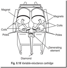
This can be done by removing the magnet from the rear of the cantilever (as in the moving magnet types) and substituting a tiny, very light, hollow piece of iron. The iron piece moves in the field of a stationary magnet, changing that field and generating a signal in the coil, Fig. 8.18.
As the armature moves toward or away from a stationary magnet pole, the reluctance (magnetic resistance) of the magnetic path changes. These cartridges are also referred to as variable-reluctance cartridges. The voltage generated is proportional to the rate of movement in the groove.
The advantages gained by lowering the moving mass are better tracking, lower distortion with all the advantages of the moving magnet types; moderate cost, high output and removable stylus assembly. This type of cartridge also requires the use of a preamplifier.
MOVING-COIL CARTRIDGES
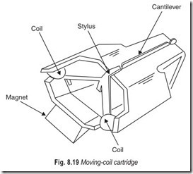
The most sophisticated and most expensive way to generate a signal is the moving-coil system. In this system carefully hand-wound coils are mounted on the cantilever and move in the field of a stationary magnet. The signal is generated directly, with a minimum amount of distortion because there are fewer losses in the transfer from mechanical to electrical signals.
To keep moving mass as low as possible there are usually very few turns of the coil. For example, stationary coils (as in moving-magnet or moving- iron cartridges) may have as many as 3,000 turns of wire. The moving coil may have only 15 or 20 turns, and fewer turns mean lower output voltage.
Unless an amplifier is already designed to work with such a cartridge, moving-coil (dynamic) models require an accessory to boost output- a preamplifier or a step-up transformer. Also, because the coils are part of the moving system, the stylus usually cannot be replaced without disconnecting the tiny wires inside the cartridge.
Moving coil cartridges have a distinctive, unmatched musical sound. This may be because the recording cutter head also operates on the moving-
coil principle and moving-coil cartridges provide an exact complement.
A dynamic cartridge is shown in Fig. 8.19. The frequency response of this cartridge extends beyond 20,000 Hz, and it gives almost as much output as a good reluctance pickup.
CERAMIC CARTRIDGES
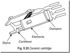
The ceramic cartridge, shown in Fig. 8.20, utilises the so-called piezoelectric effect. Movement of the cantilever, which is fixed to the stylus, applies varying forces—twists and pressures— to a special crystalline material which in turn generates the electric voltage and subsequent current. The rigid armatures required to exert this twisting force naturally increase the moving mass, and the ceramic elements are sometimes affected by heat and moisture. Although commonly used in inexpensive record players, they do not fulfill the discriminating demands of real hi-fi.
As a circuit component, a crystal cartridge acts in the same way as does a capacitor and can be considered as such.
Extremes of temperature drastically affect the operation of a crystal and its maximum sensitivity is usually at about 75 degrees. As the temperature rises above or falls below 75 degrees, the sensitivity of the crystal falls off slowly. Cartridges using barium titanate have much improved temperature characteristics. Ceramic pickups have overcome this difficulty and are now commonly used in place of crystals.
FEATURES OF STEREO CARTRIDGES
In stereophonic applications, one of the most critical components is the pickup cartridge.
The weight of a cartridge and pickup arm assembly is transmitted to the record as needle force. The maximum allowable needle force without excessive record wear is related to the size of the needle tip. Wear is dependent on pressure, which is force per unit area. The smaller the needle tip, the less the needle force must be to prevent wear. Too small a needle tip size would result in loss of tracking; that is, the needle would skate over the record instead of staying in the groove. Thus the minimum needle tip size is kept to 0.5 mill, and the range of needle force is roughly from 1/2 to 6 grams.
Frequency response is usually stated in terms of frequency range and the deviation, in dB, of the response over that range. The high limit of the range should extend to near 20,000 Hz or beyond to take full advantage of the better recordings.
The output voltage of a cartridge is important, not only because it is used to calculate how much amplification is required, but also because the higher the output the more chance there is of having a good signal-to-noise ratio. Output voltage does not establish the criteria unless the level at which the needle is driven is also specified. Standard records are used to provide the driver for output voltage tests. Manufacturers state output for either 5 cm/sec or 10 cm/sec needle velocity. The output should be higher for the greater velocity. For outputs below 10 millivolts, a separate preamplifier may be necessary, depending on the gain of the system used.
Channel separation is the indication of how well the left signal is kept out of the right channel, and the right signal out of the left channel. Good separation is necessary for good stereo effect, since the difference between the two signals is what produces the spatial effect. Tests have shown that a minimum of 15 dB separation should be maintained.
To operate properly, a cartridge must be connected to the proper amplifier input impedance. Ceramic and crystal pickups must work into a relatively high resistance (15 kilohms to several megaohms) compared with magnetic cartridges (5 to 100 kilohms). Each cartridge manufacturer specifies the specified load characteristics for his products.
Compliance is a measure of how easy it is to move the needle in the direction it must be driven during playing. It is measured in the distance, in millionths of centimetre, that the needle can be pushed by a force of 1 dyne in that direction. Stereo cartridges, Fig. 8.21, should have a high compliance in all directions of motion. That is why stereo cartridge manufacturers specify both lateral and vertical compliance. It is because of the low vertical compliance of most of the monophonic cartridges that stereo records should never be played with monophonic pickups.
Channel balance is given as the difference in dB between the output of the two channels for the same drive. The optimum arrangement is a system that is naturally balanced throughout and balance deviation of 1 dB or less should be considered good.
PLAYBACK NEEDLES
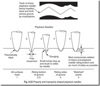
To minimise wear and secure the maximum useful life from a recording, a properly shaped needle, Fig. 8.22, must be used. A properly shaped needle will also minimise background noise.
The difference in shape between the cutting stylus and playback needle causes trackability distortion and pinch distortion. Trackability distortion is overcome by use of an elliptically shaped needle. When an elliptically shaped needle tracks the groove, its points of contact nearly coincide with the original points of cutting stylus contact at any given position. Pinch-effect distortion is caused by the changing width of the groove as the angle of groove sides and line of excursion of the cutting stylus change. As the groove width narrows, the round needle rises because it is pinched upward. Since the elliptical needle rides almost the same points of contact as the constant-width current stylus, it maintains a fairly constant vertical position.
Plain, hardened steel and osmium needles are good for only a limited number of plays and, therefore, are seldom used in hi-fi playback. A properly shaped sapphire needle will give hundreds of plays. Diamonds are also used in playback needles and are considered to be the best. Their only disadvantage is that they are very expensive and delicate and may be fractured by a slight impact.
The needle tip size for monophonic records may be over 1 mil (0.001 inch), while needle tips for stereophonic records are either 0.5 or 0.7 mil.
TONE (PICKUP) ARMS
A cartridge can deliver its full performance only if it is mounted on a tonearm of equally high quality, see Figs. 8.10 and 8.23. The tonearm’s primary function is to hold the stylus in its path while it travels across the record groove and to apply the necessary tracking force while compensating for other unwanted forces.
Modern tonearms, for use with light and small heads or cartridges, Fig. 8.23, are themselves of small mass, and have the characteristics which will permit low playing weights to be used without any problem. It is particularly important that friction of bearings should be reduced to a very small amount and the best arms have either ball races or hardened points on which to pivot. Sometimes bearing movement is damped by a viscous fluid.
Various means are found to remove resonances from parts of the frequency range where they would have ill effects. The low-frequency resonance, the frequency of which is determined by the effective mass of the whole pickup and the compliance of the head’s moving system, is generally placed in the 10–20 Hz region in recent high quality pickups.
Counterbalancing is normally by a weight behind the pivot, and this arrangement is generally adequate if the arm is not made too massive. In a few instances a spring is also used. It is not very satisfactory to use a spring to pull the arm up from the record, but a small spring may be used to pull the arm down after balancing has been done with a counterweight.
If the best stereo reproduction and minimum wear are to be achieved, the stylus must ride correctly in the record groove, without bearing more heavily on one wall than on the other. Techniques to ensure this degree of accuracy are not incorporated in the cheaper components. With a very few exceptions, record changers are inadequate from this view point; indeed, they are rarely suitable for serious listening to stereo.
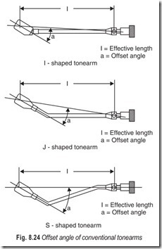
Accurate tracking will not be obtained if the arm is subject to the side-thrust which is commonly encountered in disc reproduction. Conventional arms are offset and arranged so that the stylus will fall in front of the record centre. This is done to minimise tracking error. The result is normally a maximum tracking error of 3 degrees with minimum error at the centre. Unfortunately, this arrangement, allied to the friction of the stylus in the groove, causes the arm to swing inwards. This aspect of arm design has received considerable attention in the last few years and in some modern tonearms a simple device is incorporated to correct side thrust. For instance, a small weight can be arranged in such a way that it will just correct the side thrust by pulling on the arm.
The cartridge assembly is at an angle, (a) to the arm’s axis, the line connecting the stylus tip to the arm’s pivot. This is called the offset angle, Fig. 8.24, and its purpose is to minimise the tonearm’s tracking error. Tracking error is the angle that the cartridge axis deviates from a tangent line to the record at any given point on the record. The smaller the tracking error, the better.
Some form of mechanical aid for lifting and lowering is essential if a very small playing weight is used. A number of arms have in-built devices, but separate accessories can be obtained for arms which lack this facility.
TURNTABLE
The term turntable refers to a composite of parts; the platter on which the record rests, the motor and drive system, the tonearm, the cartridge and the housing for the entire assembly.
The platter and drive assembly revolve the record at a specific speed. The tonearm holds the cartridge and suspends it over the record. The stylus in the cartridge traces the record groove. The housing contains the various components and stops vibrations from adversely affecting performance.
The basic turntable has fewer in-built mechanical devices to degrade performance—which means sound quality will be improved. Fewer parts also means there is less likelihood of break down.
A basic turntable plays only long play (LP) records, has one speed (33.33 rpm), is manual, and usually devoid of cosmetic frills. In other words, it’s a single-play unit.
Just because a turntable is basic doesn’t necessarily mean it’s cheap. Most high performance, high cost models are of the basic type and are quite spartan in appearance.
All turntables revolve at 33.33 rpm, the speed required for LP record reproduction. For playing singles– 170 mm and 300 mm diameter—a unit with 45 rpm is also required. Record collectors with archives of old discs may also need 78 rpm.
The turntable speed is consistent and the motor and drive system must revolve the platter (and the record) at the exact required speed. Any deviation in speed is known as speed error or wow and flutter.
All turntables exhibit some form of speed error but most slowing or speeding effects are so miniscule they are inaudible (if they are not you can hear them quite clearly).
Turntables with a feature called quartz lock incorporate electronic speed corrrection, where the speed of the platter is continually referenced against the unwavering oscillation of a quartz crystal. When a variation in speed is sensed, the circuitry compensates for it.
The way speed is changed is also a factor. Electronic switching is silent and doesn’t cause as many undesirable vibrations as mechanical switching.
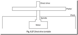
Belt drive produces better performance while direct drive permits a greater degree of sophistication. Both drive systems are comprised of a number of parts—the motor, its connection to the platter and the spindle on which the platter sits.
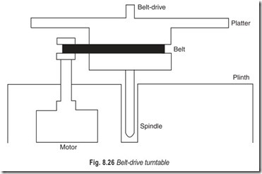
In a belt-drive turntable the motor turns a spindle with a pulley attached to it. A belt wrapped around the pulley and the platter rotates the latter at the desired speed (see Fig. 8.26).
The motor in any turntable is a notorious source of noise and vibration which can degrade performance. The neoprene belt in a belt drive system helps to decouple the motor from the platter and thereby reduce the transmission of these unwanted energies. The belt also helps in isolating the stylus from outside influences.
In a direct-drive turntable, Fig. 8.27 and 8.28, the platter rests on a spindle which is connected to the motor. There are no belts or pulleys and the platter is driven directly, hence its name. The platter’s connection to the motor means vibrations and noise from the turntable and outside can be more easily transmitted.
The performance of belt-drive and direct-drive turntables are compared and it is reasonable to expect an expensive direct-drive model would outperform a cheap belt-drive unit and vice-versa.
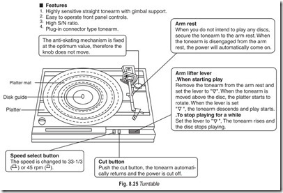
Every turntable needs a housing to contain its components and like the other sections of the turntable it is comprised of a number of parts (see Fig. 8.25); the baseboard, plinth, feet and cover. Manufacturers frequently use materials which tend to block or restrict the transmission of vibrations. In addition to its engineering significance, the housing dictates the overall aesthetics of the turntable.
The baseboard supports the tonearm, platter housing, function controls and sometimes the motor. It must be rigid and solid but more importantly it must be isolated from the main plinth. Some manufacturers use springs, rubber or other materials to restrict transmission of vibrations, but the effectiveness of the design is more important than the design itself.
The plinth supports the entire turntable and rests on shock-absorbing feet. These feet form a barrier where the turntable and its resting place meet.
Footsteps set up mechanical vibrations which travel to the turntable. The housing’s feet must absorb these vibrations to stop them from reaching the stylus. It’s handy if footsteps are adjustable so the turntable can be accurately levelled.
The cover does more than keep out the dust. In most designs it is made from heavy duty perspex which prevents airborne vibrations such as sound waves interfering with stylus operation.
EXERCISES
Descriptive Questions
1. Describe the various steps involved in making records.
2. Briefly explain stereo pickup techniques.
3. What are the different systems of stereo recording?
4. Explain the following :
(a) Tracking weight (b) Tracking error
(c) Cantilever (d) Channel balance
(e) Channel separation. (f) Microgroove
5. With the help of a suitable sketch explain the working of a moving-coil cartridge.
6. What are the features of a stereo cartridge?
7. Briefly explain the parts of a turntable.
8. What is the difference between a belt drive turntable and a direct drive turntable? Which drive is preferred and why?
Multiple Choice Questions
1. Stereo records are produced by
(a) lateral movement of the record cutter
(b) vertical movement of the record cutter
(c) lateral and vertical movement of the record cutter
(d) none of the above
2. Tracking weight is usually
(a) one to two grams (b) two to three grams
(c) three to four grams (d) none of the above
3. The majority of high quality cartridges use
(a) elliptical stylus (b) spherical stylus
(c) fine-line stylus (d) none of the above
4. The magnetic pickup is a
(a) current-operated device (b) voltage-operated device
5. To improve tracking the moving mass of the cartridge must be
(a) lowered (b) raised
6. The most sophisticated and expensive way to generate a signal is
(a) the moving magnet system (b) the moving-iron system
(c) the moving-coil system (d) none of the above
7. Ceramic cartridges utilise
(a) electromagnetic induction (b) piezoelectric effect
(c) either (a) or (b) (d) neither (a) nor (b)
8. The weight of a cartridge and pickup arm assembly is transmitted to the record as
(a) tracking force (b) needle force
(c) both (a) and (b) (d) neither (a) nor (b)
9. The output voltage of a cartridge is important because
(a) it is used to calculate how much amplification is required
(b) it forms the basis for signal to noise ratio
(c) both (a) and (b)
(d) neither (a) nor (b)
10. Stereo cartridge manufacturers specify
(a) lateral compliance (b) vertical compliance
(c) both (a) and (b) (d) neither (a) nor (b)
11. The difference in dB between the output of the two channels for the same drive is called
(a) tracking error (b) tuning error
(c) channel balance (d) none of the above
12. Trackability distortion is overcome by the use of
(a) an elliptically shaped needle (b) a spherical shaped needle
(c) either (a) or (b) (d) neither (a) nor (b)
13. Tracking will not be obtained if the arm is subject to
(a) vertical thrust (b) lateral thrust
(c) neither (a) nor (b) (d) either (a) or (b)
14. In-built mechanical devices
(a) upgrade performance (b) degrade performance
15. Turntables with quartz lock incorporate
(a) electronic speed correction (b) mechanical speed correction
Fill in the Blanks
1. The multiple channels recorded in the studio are …………………………before a record is cut.
2. In the standard recording process microphones feed the signals to………………………….
3. When a master tape is played its magnetic patterns are converted to………………………….
4. The stereo effect is obtained by proper………………………… of the microphones.
5. The stylus is the only part to make…………………………with the record.
6. The cantilever transmits its motions to the…………………………system.
7. The actual number of grooves will depend on the…………………………between adjacent grooves.
8. Moving-coil cartridges require an accessory to …………………………output.
9. The maximum sensitivity of a crystal is at about………………………… degrees.
10. To operate properly a cartridge must be connected to the proper amplifier ………………………….
11. Stereo records should never be played with …………………………pickups.
12. Most tone arms have small………………………….
13. Any deviation in speed is known as…………………………and………………………….
14. Footsteps of a turntable must be………………………….
ANSWERS
Multiple Choice Questions
|
1. (c) |
2. (a) |
3. (a) |
4. (a) |
5. (a) |
6. (c) |
|
7. (b) |
8. (a) |
9. (c) |
10. (c) |
11. (c) |
12. (a) |
|
13. (b) |
14. (b) |
15. (a) |
Fill in the Blanks
|
1. mixed |
2. preamplifiers |
3. electrical signals |
|
4. placement |
5. contact |
6. generating |
|
7. spacing |
8. boost |
9. 75 |
|
10. impedance 13. wow, flutter |
11. mono 14. adjustable |
12. mass |
![FIG.-8.13-The-dimensions-of-the_thum[1] FIG.-8.13-The-dimensions-of-the_thum[1]](http://machineryequipmentonline.com/electric-equipment/wp-content/uploads/2020/07/FIG.-8.13-The-dimensions-of-the_thum1_thumb.jpg)
![Fig.-8.14-The-reproducing-stylus-is_[2] Fig.-8.14-The-reproducing-stylus-is_[2]](http://machineryequipmentonline.com/electric-equipment/wp-content/uploads/2020/07/Fig.-8.14-The-reproducing-stylus-is_2_thumb.jpg)
![Fig.-8.15-The-groove-of-a-gramophone[1] Fig.-8.15-The-groove-of-a-gramophone[1]](http://machineryequipmentonline.com/electric-equipment/wp-content/uploads/2020/07/Fig.-8.15-The-groove-of-a-gramophone1_thumb.jpg)
![Fig.-8.16-Mono-grooves-with-a-latera[2] Fig.-8.16-Mono-grooves-with-a-latera[2]](http://machineryequipmentonline.com/electric-equipment/wp-content/uploads/2020/07/Fig.-8.16-Mono-grooves-with-a-latera2_thumb.jpg)

![Fig.-8.17-Moving-magnet-cartridge_th[1] Fig.-8.17-Moving-magnet-cartridge_th[1]](http://machineryequipmentonline.com/electric-equipment/wp-content/uploads/2020/07/Fig.-8.17-Moving-magnet-cartridge_th1_thumb.jpg)
![Fig.-8.21-Basic-stereo-cartridge-ope[2] Fig.-8.21-Basic-stereo-cartridge-ope[2]](http://machineryequipmentonline.com/electric-equipment/wp-content/uploads/2020/07/Fig.-8.21-Basic-stereo-cartridge-ope2_thumb.jpg)
![Fig.-8.23-Modern-tonearms-for-use-wi[2] Fig.-8.23-Modern-tonearms-for-use-wi[2]](http://machineryequipmentonline.com/electric-equipment/wp-content/uploads/2020/07/Fig.-8.23-Modern-tonearms-for-use-wi2_thumb.jpg)
![Fig.-8.28-Construction-of-coreless-d[2] Fig.-8.28-Construction-of-coreless-d[2]](http://machineryequipmentonline.com/electric-equipment/wp-content/uploads/2020/07/Fig.-8.28-Construction-of-coreless-d2_thumb.jpg)