Motor Control—3 Phase
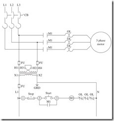
Figure A-1 Typical motor control circuit. Components: CB, 3-phase circuit breaker with thermal trip units; OL, motor thermal overloads; FU, fuse rated to protect the control circuit; control transformer configured for high- voltage input low-voltage output; Stop, Normally Closed push button; Start, Normally Open push button; M1, low-voltage control coil part of the motor controller.
Ladder Diagrams
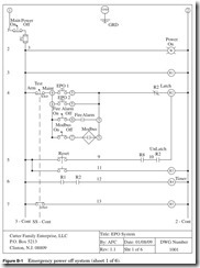
Figure B-1 Emergency power off system (sheet 1 of 6).
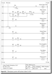
Figure B-2 Emergency power off system (sheet 2 of 6).
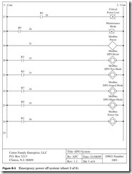
Figure B-3 Emergency power off system (sheet 3 of 6).
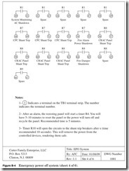
Figure B-4 Emergency power off system (sheet 4 of 6).
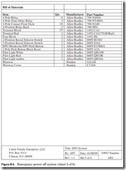
Figure B-5 Emergency power off system (sheet 5 of 6).
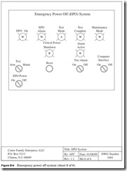
Figure B-6 Emergency power off system (sheet 6 of 6).
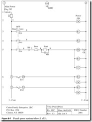
Figure B-7 Punch press system (sheet 1 of 3).
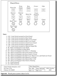
Figure B-8 Punch press system (sheet 2 of 3).
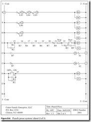
Figure B-9 Punch press system (sheet 3 of 3).
DGH Corporation Modules
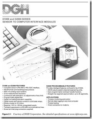
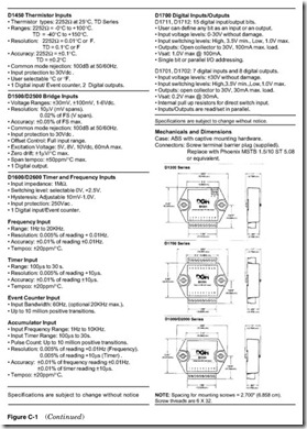
Figure C-1 Courtesy of DGH Corporation. See detailed specifications at www.dghcorp.com.
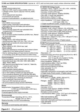
Figure C-1 (Continued
Figure C-1 (Continued)
Figure C-1 (Continued)
Figure C-1 (Continued)
Figure C-1 (Continued)
Figure C-1 (Continued)
Figure C-1 (Continued)
Figure C-1 (Continued)
Figure C-1 (Continued)
![clip_image002[5] clip_image002[5]](http://machineryequipmentonline.com/electric-equipment/wp-content/uploads/2020/06/clip_image0025_thumb.jpg)
![clip_image002[7] clip_image002[7]](http://machineryequipmentonline.com/electric-equipment/wp-content/uploads/2020/06/clip_image0027_thumb.jpg)
![clip_image002[9] clip_image002[9]](http://machineryequipmentonline.com/electric-equipment/wp-content/uploads/2020/06/clip_image0029_thumb.jpg)
![clip_image002[11] clip_image002[11]](http://machineryequipmentonline.com/electric-equipment/wp-content/uploads/2020/06/clip_image00211_thumb.jpg)
![clip_image002[13] clip_image002[13]](http://machineryequipmentonline.com/electric-equipment/wp-content/uploads/2020/06/clip_image00213_thumb.jpg)
![clip_image002[15] clip_image002[15]](http://machineryequipmentonline.com/electric-equipment/wp-content/uploads/2020/06/clip_image00215_thumb.jpg)
![clip_image002[17] clip_image002[17]](http://machineryequipmentonline.com/electric-equipment/wp-content/uploads/2020/06/clip_image00217_thumb.jpg)