RF And if Amplifiers
rf (radio-frequency) amplifiers usually are the first stage in AM, FM, or TV receivers and are similar to other amplifiers. They differ primarily in the frequency spectrum over which they operate, which is 10,000 hertz to 30,000 megahertz. There are two classes of RF amplifiers: untuned and tuned. In an untuned amplifier, a response is desired over a large RF range, and the main function is amplification. In a tuned amplifier, high amplification is desired over a small range of frequencies or a single frequency. Normally, when RF amplifiers are mentioned, they are assumed to be tuned unless otherwise specified.
In receiving equipment, the RF amplifier serves to amplify the signal and select the proper frequency. In transmitters, the RF amplifier serves to amplify a single frequency for application to the antenna. Basically, the receiver RF amplifier is a voltage amplifier, and the transmitter RF amplifier is a power amplifier.
In a receiver circuit, the RF amplifier must provide sufficient gain, produce low internal noise, provide good selectivity, and respond well to the selected frequencies.
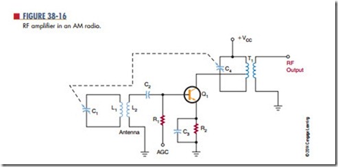
Figure 38-16 shows an RF amplifier used for an AM radio. Capacitors C1 and C4 tune the antenna and the output transformer T1 to the same frequency.
The input signal is magnetically coupled to the base of transistor Q1. Transistor Q1 operates as a class A amplifier. Capacitor C4 and transformer T1 provide a high voltage gain at the resonant frequency for the col- lector load circuit. Transformer T1 is tapped to provide a good impedance match for the transistor.
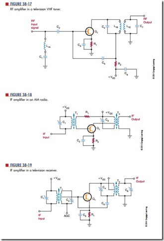
Figure 38-17 shows an RF amplifier used in a tele- vision VHF tuner. The circuit is tuned by coils L1A, L1B, and L1C. When the channel selector is turned, a new set of coils is switched into the circuit. This provides the necessary bandwidth response for each channel. The input signal is developed across the tuned circuit consisting of L1A, C1, and C2. Transistor Q1 operates as a class A amplifier. The collector-output circuit is a double-tuned transformer. Coil L1B is tuned by capaci- tor C4, and coil L1C is tuned by capacitor C7. Resistor R2 and capacitor C6 form a decoupling filter to prevent any RF from entering the power supply to interact with other circuits.
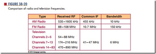
In an AM radio, the incoming RF signal is converted to a constant if (intermediate frequency) signal. A fixed-tuned IF amplifier is then used to in- crease the signal to a usable level. The if amplifier is a single-frequency amplifier. Typically, two or more IF amplifiers are used to increase the signal to the proper level. The sensitivity of a receiver is deter- mined by its signal-to-noise (S/N) ratio. The higher the gain, the better the sensitivity. Figure 38-18 shows a typical IF amplifier in an AM radio. The IF frequency is 455,000 hertz. Figure 38-19 shows an IF amplifier in a television receiver. Figure 38-20 compares the frequencies of radio and television receivers.
Questions
1. How do RF amplifiers differ from other amplifiers?
2. What are the two types of RF amplifiers?
3. Where are RF amplifiers used?
4. What is an IF amplifier?
5. What is significant about an IF amplifier?


