Today, alternating current is the most used method to transmit electrical energy from one location to another. This was not the case in the late 1800s. Thomas Edison utilized direct current. His vision of electrified cities incorporated the idea of many small, DC-generating stations scattered about in the community, because there was no way to change or alter direct current to recoup transmission losses. This limited the usefulness of DC to small, local areas and prohibited its usefulness in transmitting electrical energy over long distances.
In 1888, a young engineer discovered rotating magnetic fields and their potential for the practical generation and transmission of electrical energy that made the electrification of the United States and the rest of the world possible. The power lines that crisscross the cities and countryside are a testament to his genius. The father of alternating current and our electrified world was Nikola Tesla.
This chapter examines the reasons alternating current is important, the methods by which it is generated, and its important electrical characteristics.
Generating alternating Current
An AC generator converts mechanical energy into electrical energy. The AC generator, also called an alternator, is capable of producing an alternating voltage by utilizing the principles of electromagnetic induction. Electromagnetic induction is the process of inducing a voltage in a conductor by passing it through a magnetic field.
As described in Chapter 18, the left-hand rule for generators can be used to determine the direction of current flow in a conductor that is being passed through a magnetic field: When the thumb is pointed in the direction of the conductor movement, the index finger (extended at right angles to the thumb) indicates the direction of the magnetic lines of flux from north to south, and the middle finger (extended at a right angle to the index finger) indicates the direction of current flow in the conductor. Maximum voltage is induced when the conductor is moved perpendicular to the lines of flux. When the conductor is moved parallel to the lines of flux, no voltage is induced.
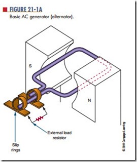
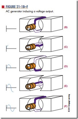
Figure 21-1A through 21-1F shows a wire loop being rotated through a magnetic field. In position B, the loop is parallel to the lines of force. As previously stated, no voltage is induced when the conductor is moved parallel to the lines of force. As the loop is rotated to position C, it passes through more lines of force, and the maximum voltage is induced when the loop is at right angles to the lines of force. As the loop continues to rotate to position D, fewer lines of force are cut and the induced voltage decreases. Movement from position B to position D represents a rotation of 180º. Rotating the loop to position E results in a reversal of current flow. Again, the maximum voltage is induced when the loop is at right angles to the lines of force. As the loop returns to its original position at F, the induced voltage returns to 0.
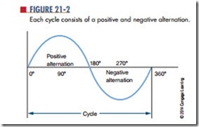
Each time an AC generator moves through one complete revolution, it is said to complete one cycle. Its output voltage is referred to as one cycle of output voltage. Similarly, the generator produces one cycle of
output current in a complete circuit. The two halves of a cycle are referred to as alternations (Figure 21-2). Each alternation is produced by a change in the polarity of the voltage. The voltage exhibits one polarity during half of the cycle (one alternation) and the opposite polarity during the other half of the cycle (second alter-nation). Generally, one alternation is referred to as the positive alternation and the other as the negative alter- nation. The positive alternation produces output with a positive polarity; the negative alternation produces output with a negative polarity. Two complete alternations of voltage with no reference to time make up a cycle. One cycle per second is defined as a hertz (Hz).
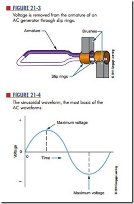
The rotating loop of wire is referred to as the armature. The AC voltage that is induced in the rotating armature is removed from the ends of the loop by a sliding contact located at each end of the armature (Figure 21-3). Two metal rings, called slip rings, are attached to each end of the loop. Brushes slide against the slip rings to remove the AC voltage. The AC generator described generates a low voltage. To be practical, an AC generator must be made of many loops to increase the induced voltage.
The waveform produced by an AC generator is called a sinusoidal waveform or sine wave for short (Figure 21-4). The sine wave is the most basic
and widely used of all the AC waveforms and can be produced by both mechanical and electronic meth- ods. The sine wave is identical to the trigonometric sine function. The values of a sine wave vary from 0 to maximum in the same manner as the sine value. Both voltage and current exist in sine-wave form.
Questions
1. What is the function of an AC generator?
2. Explain how an AC generator operates.
3. Define the following terms:
a. Cycle
b. Alternation
c. Hertz
d. sine wave
4. Identify the major parts of an AC generator.
5. What is the difference between a positive and a negative alternation?
Would it be possible to design an AC generator whose armature generates the magnetic field and rotates, thus inducing an AC current in stationary coils placed around it?


