Frequency Counters
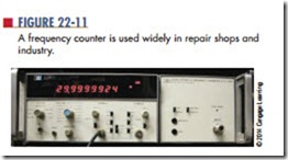
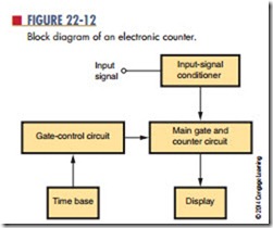
A frequency counter (Figure 22-11) measures frequency by comparing a known frequency against an input frequency. All frequency counters consist of the same basic sections: a time base, an input-signal conditioner, a gate-control circuit, a main gate, a decade counter, and a display (Figure 22-12). The signal conditioner converts the input signal to a wave shape and amplitude compatible with the circuitry in the counter. The main gate passes the conditioned input signal to the counter circuit if a signal from the time base is present at the same time. The time base drives the gate-control circuit, using a signal compatible with
the signal being measured. The gate control acts as the synchronization center of the counter. It controls the opening and closing of the main gate and also pro- vides a signal to latch (lock onto) the count at the end of the counting period and reset the circuitry for the next count. The decade counter keeps a running tally of all the pulses that pass through the main gate. One decade counter is required for each digit displayed. The display, which provides a visual readout of the frequency being measured, can be of several types. The more common displays are gas-discharge tubes; light-emitting diode displays (LEDs), and liquid crystal displays (LCDs).
The electronic counter was once a piece of laboratory equipment but is now used in electronics repair shops, engineering departments, and ham-radio shacks, and on industrial production lines. The wide use of the counter can be attributed to the integrated circuit, which has reduced the size and price of the counter while increasing its accuracy, stability, reliability, and frequency range. (Integrated circuits are discussed in Section 4.)
Questions
1. What is the function of an electronic counter?
2. What are the basic sections of a counter?
3. Draw and label a block diagram of an electronic counter.
4. What is the function of the signal conditioner in a counter?
5. Why has the counter increased in popularity?

