Root Locus Method
It was shown that the stability of control system could be studied by the roots of characteristic equation. In this section, the Root Locus will be studied for a second order system. For higher order system there, is an analytical approach that can be used to plot the Root Locus from the open loop transfer equation. The method is tedious and the loci are plotted from the zeros and poles of the open loop transfer function. It should be mentioned that the number of loci are equal of the order of the characteristic equation. The loci will end to the zeros or infinity as the gain of the system is increased.
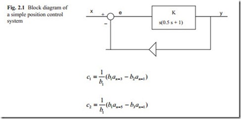
The block diagram of a negative feedback of a simple servo position control is shown in Fig. 2.1. The integrator shows the fact that the position is obtained from velocity and the first order lag shows that because of the inertia there is a time lag.
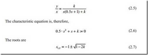
The closed loop transfer function can be obtained by using the block diagram algebra. With some manipulation it can be shown that the closed loop transfer function becomes
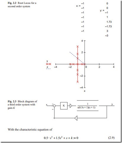
Now the root locus can be obtained by varying k from zero to infinity. Some important points are the roots when k = 0, k = 0.5 and k > 0.5. For k < 0.5, the roots are negative starting from the points 0 and − 2. And there is a breakaway point at point k = 0.5 where the roots becomes complex and as k is increased, the two complex roots move towards infinity parallel to the imaginary axis. By comparing the trans- fer function with the second order transfer function studied in previous chapter, it can be shown that
The Root Locus for the above second order system is shown in Fig. 2.2. X and Y contain the real and imaginary part of the root for values of Gain ( K). In this case, there are two loci, which end at infinity. The roots are shown by crosses.
Figure 2.3 shows a simple third order transfer function which could represent a position control system with DC motor.
This model contains the effect of inductance in the system. In the open loop transfer function, there is an integrator and two first order lags. Therefore, there are three poles at s = 0, s = − 1, s = − 2. The loci start at these three poles and end to infinity as the gain K is increased. It should be noted that there is no zeros, which makes the numerator of the open loop transfer function equal to zero. The closed loop transfer function may be calculated as
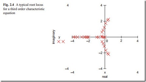
The MathCAD Polyroots expression can be used to calculate the roots of character- istic equation for various K. The root locus for this system is shown in Fig. 2.4. At K = 0, there are three negative real roots. As K is increased the two real roots move towards each other and the third real root moves towards infinity. The two real roots break away from the real axis and become complex. As k is increased, the real part of complex roots becomes positive showing that the system becomes unstable. The root locus in this case enter the right-hand side of the s-plane.
The root locus for this system is shown in Fig. 2.4. Higher order systems have more roots and the root locus becomes more complicated. There are also computer programs, which presents the root locus from the open loop transfer function re- moving the need to calculate the closed loop transfer function. In this book, the MathCAD computer program is used throughout to plot the root locus. There are also methods of calculating the gain for each location of the roots. With MathCAD polyroots facility, the roots can be calculated for each gain or parameter of interest separately. The correct gain or parameter of interest can be obtained by inspection of the table of roots and there is no need to go into details of the graphical methods.
There are computer programs that can calculate the roots of characteristic equation of any order. MatLab and MathCAD are two of the most commonly used com- puter programs. The Root Locus can then be plotted. The damping ratio indicated by the real part and the frequency of oscillation is determined by the imaginary part. For most control systems, a damping ratio of 0.7–1 is preferred. The damping ratio of 0.7 will result in small overshoot and the damping ratio of 1 results in no overshoot. This means that all roots must lie between the ± 45° lines on the left side of the s-plane.
For stability all roots must lie in the left hand side of the s-plane and the imaginary part show in fact the frequencies of oscillation. The further away from the origin the faster the response to a step input. For a good response to step input all roots must lie in the 45° and the negative real axis. For complicated system which have many roots the root nearest to the imaginary axis dominates the step input response.
