CYLINDER BORE DISTORTION
If someone were able to make an ideal engine it would consist of perfectly round and straight cyl inder bores and perfectly round and straight pis tons which slide up and down in these bores. Un fortunately this ideal can only be approxima tely realized.
When the cylinder block is manufactured the bores are round and straight within much less than a thousandth of an inch. But bolting the cylinder head in place distorts the straightness of the bore and may even pull it a little out of round . To keep this distortion to a minimum, car manu facturers specify just how tight the cylinder head bolts should be. Bolts too tight will cause undue distortion. On the other hand, if bolts are too loose, leakage will occur at the gasket. In order to tighten the bolts just the proper amount it is desirable to use a torque wrench. This wrench indicates the pull in pounds that are applied to the wrench. Each car maker issues instructions as to how much the pull should be.
The cylinder bores are machined at room temperature but in an actual engine the temperature is a few hundred degrees higher. Metals expand when they are heated. If an engine had bores which were not attached to the block, no appre ciable distortion would occur when they were heated but unfortunately the bores are usually an integral part of the cylinder block which is an unsymmetrical piece of metal which includes water jackets, valve chambers and upper half of crank case, Fig. 43. These parts expand in different ways with the result that the bores are distorted when heated.
PISTONS
The piston likewise is straight when it is manu factured (at room temperature). Whether it is made round or slightly oval depends on its design . An oval piston when cold may be p ractically round when hot.
Neither the cylinder bore n.or the piston skirt is perfectly stiff which means that both th e gas pressures and the inertia pressures acting on the piston slightly distort the wearing surfaces of both bore and piston skirt. ·
A small amount of clearance between piston and cylinder bore must be allowed for the oil :S.lm which must coat both surfaces in order to sup press wear. Some additional clearance between piston and cylinder bore is required when the engine is cold because the piston expands mor e rapidly than the cylinder bore as the engine warms up because the piston is hotter than the bore when the engine is operating.
Although cylinder bore distortion and piston skirt distortion only amount to a few thousandths of an inch, the result is importa t w n it .:i , remembered that a piston in a typical en-gine;”·
operating at a speed of 4,000 rpm travels at an ‘ average speed of half a mile per minute.
Aluminum Pistons
Ordinary aluminum alloy pistons expand at about twice the rate of the cast iron bore. There fore, special provi ions are made in aluminum alloy piston designs to control piston expansion. There is, however, a special silicon-aluminum al loy with a low expansion rate used in some pistons.
All other aluminum alloy pistons have special design features so that the clearance when cold is not enough to permit objectionable slap and yet when the piston becomes hot there is still enough clearance so there is no danger of the piston stick ing in the bore.
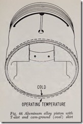
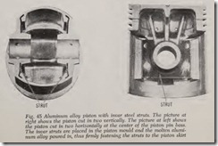
Numerous types of aluminum alloy pistons have been introduced, all designed to take care of the expansion problem in one way or another. How ever, it would serve no useful purpose to describe all the various designs here. Instead, the two types in common use will be discussed, namely: The T slot piston with “cam-ground” skirt, Fig. 44 and the invar strut piston, Fig. 45. lnvar is a steel alloy containing about 36 per cent of nickel. The expan sion rate of invar is practically zero. Both pistons are slotted horizontally between the head and skirt in order to provide a heat dam to reduce the amount of heat flowing from piston head to skirt and thereby reduce skirt expansion.
Returning to the T-slot design, Fig. 44, it will be seen that the T-slot is formed by a horizontal slot between the piston head and piston skirt which connects with a nearly vertical slot in the piston skirt. The opposite side of the piston has a hori zontal slot but no vertical slot. The horizontal slots act as heat dams to prevent undue heat from flowing from piston head to skirt. The nearly vertical slot provides enough flexibility in the skirt to discourage the possibility of the skirt sticking fast in the bore. The skirt is relieved (under cut) in the region of the piston pin hole so that any undue expansion in this region will not cause the piston to seize in the bore. Too much flexibility in the skirt, however, is undesirable and it is for this reason that the slot is not continued all the way down through the lower edge of the skirt. The slot length shown gives the desired flexibility. Too much flexibility would permit rocking of the piston in the bore and would in time slightly round off the outer surfaces of the piston rings and thus render them less effective against leak age of both gas pressure and oil.
If the slot in the skirt were vertical it would gradually make a ridge in the bore. To avoid this the slot is slightly diagonal.
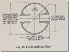
The skirt of the piston is ground slightly ellipti cal, Fig. 46. In a typical case , the piston diam eter is .006″ less when measured across the piston pin holes than when measur ed across the “large” diameter. The elliptical piston is called a cam ground piston because the grinding wheel position is controlled by an elliptical cam. Note that with a cam-ground piston the front and rear surfaces may not contact the bore at all. The terms front and rear mean front and rear with respect to the engine block.
The skirt of the cam-ground T-slotted piston may be fitted to the cylinder bore with close clearance in a cold engine. When the engine be comes warm and the piston expands, the skirt (because of the T-slot) tends to shape itself to the cylinder bore without any danger of the piston sticking in the bore.
Piston Side Thrust
When a piston moves down on its power stroke, the angularity of the connecting rod causes it to be pressed against the cylinder bore surface which is opposite the crankpin, Fig. 47. This side of the piston is often called the major pressure side or major thrust side while the other side is called the minor pressure side. Many car makers recommend that the T-slot be located on the camshaft side, thus enabling the stiffer major pressure side of the piston to resist the side thrust caused by combus tion pressure.
However, at high speed the inertia forces acting on the piston are greater than those caused by gas pressure and they act alternately on both sides of the piston as it moves up and down. As the piston rushes down it presses against one side of the bore and as it rushes upward it presses against the other. Therefore both sides of the piston are sub jected to the same inertia side thrusts during each revolution of thP engine. Gas pressures and inertia pressures should be considered separately.
At low speed, when inertia forces are low, gas pressure is high when the throttle is open. There fore, some engine manufacturers place the T-slot on the major pressure side because the resilient T slotted skirt cushions tendency to piston slap.
To sum up, the T-slotted aluminum cam ground piston is able to work successfully in a cast iron cylinder bore for three reasons, namely: ( 1) Flex ible skirt obtained by (nearly) vertical slot. ( 2) Cam grinding (oval) which enables the piston to fit itself to the bore automatically. ( 3) Heat dam which prevents most of the heat on the piston head from reaching the skirt.
The skirt is flexible circumferent ially. Longi tudinally the skirt is rigid enough so that it does not wobble in the bore; also the skirt has sufficient lengthwise rigidity so the outer faces of the rings move straight up and down in the bore. By con trast, a skirt that is flexible lengthwise would cause the outer faces of the rings to wear round and thus reduce their effectiveness.
Coated Pistons
On some engines the piston skirt is coated with some special material in order to prevent scuffing (scratching) of the skirt and bore. In addition some of these coatings arc porous and therefore
absorb oil which assists in lubricating both the skirt and the bore, thereby reducing wear. The coating may be a thin film of tin or cadmium plating. Tin and cadmium are soft and ductile metals and therefore are unable to scuff the bore.
Chemical coatings are used on many aluminum pistons. The coating is chemically attached to the aluminum. It is soft, brittle and porous. Because it is soft and brittle, scuffing of the bore is avoided. Being porous, it permits the coating to soak up oil which aids lubrication.
These special coatings for both cast iron and aluminum pistons practically prevent scuffing under the following three conditions:
( 1) When the engine is first started from cold before the oil is warm enough to reach the cylin der bores and piston skirts.
( 2) When the engine is new at which time the coatings are almost a perfect guarantee against scuffing and piston sticking.
( 3) When the engine is operated under extremely high temperature conditions caused by continuous fast running, defects in cooling and lubrication system, and excessively high air tem perature, the possibility of scuffing or piston stick ing will either be tremendously reduced or en tirely eliminated by the coating.
When the engine is new, the piston should move up and down exactly parallel to the cylinder bore. The clearance between skirt and bore is small enough so that there is no appreciable rock ing of the piston in the bore.
A straight up and down motion of the piston enables the outer surfaces of the piston rings to press effectively against the bore and also permits them to function exactly the way they were de signed to do. On the other hand, after excessive wear of skirts and bore, the rocking of the piston will round the outer faces of the piston rings and therefore reduce their ability to prevent gas leak age as well as their ability to control oil consumption.
PISTON RINGS
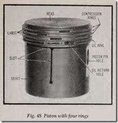
Piston rings are circular springs, Fig. 48, which are cut in two at one point so that they may be slipped over the piston. They are made somewhat larger than the cylinder bore so that when in stalled on the piston and inserted in th e bore they will press against the bor e. With th e piston in stalled in the bore, the gap between the two ends of the ring range upwards of .007” depending on the engine. As to the actual gap for a given
engine, car maker’s instructions should be fol lowed. The purpose of the gap is to prevent the two ends of the ring from butting and therefore binding when the ring expands when the engine is hot. Gaps on adjoining rings should be half a circumference apart in order to minimize leakage from one ring gap to another. In Fig. 48, the gaps of all four rings are shown close together for purposes of illustration. Actually, the gaps of any two adjacent rings should be staggered one-half a circumference apart.
At low engine speed, the rings are able to follow the slightly wavy surface of the bore exactly but at high speeds they may leap and bounce, hitting the high spots but skipping the low ones. This action results in extra leakage of gas pressure from the combustion chamber to the crankcase, and also it results in extra oil flowing from the crankcase to the combustion chamber where it is burned and therefore wasted.
Automobile pistons ordinarily are equipped with three or four rings. Only rarely has a piston with five rings been used.
With a three-ring piston, the upper two rings are intended particularly to seal the piston against leakage of gas pressure while the lower ring is designed to prevent too much oil from passing into the combustion chamber. The upper two rings are called compression rings; the lower ring is called an oil control ring or simply an oil ring. If the piston has four rings, the two upper ones are usually compression rings and the two lower for oil control. However, the piston shown in Fig. 48 has three compression rings and one oil ring.
Oil control rings are slotted. Behind the slots are drain holes in the piston skirt so that excess oil scraped from the cylinder bore by the ring is returned to the crankcase. If the slots in the oil rings become filled with carbon, gum or sludge, the oil consumption may be excessive because the extra oil scraped off the cylinder walls cannot drain back through the piston skirt into the crank case. The same remark holds true concerning clogging of the drain holes in the bottom of the piston ring grooves.
PISTON PINS
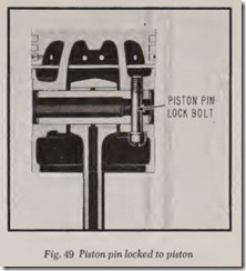
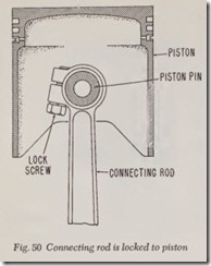
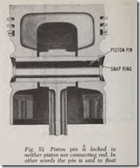
There are four ways that the connecting rod may be attached to the piston, as follows: ( 1) The pin may be locked to one of the piston boss es, Fig. 49, in which case th e rod oscillates on the pin. ( 2) The rod may be locked to th e pin which oscillates in th e bosses, Fig. 50. (3) The pin may be free to oscillate within its boss es and within the rod, Fig.51. In this case the pin is prevented from touching (and scuffing or scoring) the cylinder bore by the use of snap rings at its ends. This is called a floating pin. ( 4) The pin may be a tight press fit in the connecting rod and is free to oscillate in the piston. Due to its pressed fit the necessity of the snap rings shown in Fig. 51is eliminated.
CRANKSHAFT & MAIN BEARINGS
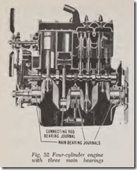
Crankshafts are supported by two or more plain bearings. The term “plain” simply means that the bearing has a smooth surface of suitable material. (Ball or roller bearings are not used on crank shafts on modern American automobiles). Fig. 52 illustrates a crankshaft for a four-cylinder engine supported in three plain bearings. These bearings are called main bearings in order to distinguish them from the plain bearings in the lower ends of the connecting rods (called connecting-rod bear ings or crankpin bearings).
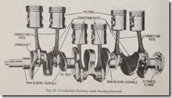
Those portions of the crankshaft which are enclosed by main or rod bearings are called main bearing journals or connecting-rod journals, re· spectively, Fig. 53.
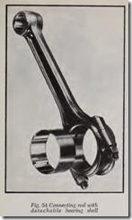
Nowadays all automobile engines use extremely thin shell main and rod bearings, Fig. 54. These bearings are called precision insert bearings. Their thickness varies but may be as little as .050″. The back of the bearing is made of a strip of steel which is coated with a bearing alloy (such as babbitt) which ranges in thickness from .002″ to .006″ depending on the bearing. The strip is then cut to length and pressed into semi-circular form.
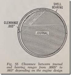
Ideally, a bearing never touches its journal be cause the two are separated by an oil film. How ever, in actual practice they do contact each other under favorable conditions. In a typical auto mobile engine the clearance between journal and bearing may range from .0005″ to .003″ depend ing on the engine design. The clearance just men tioned is the total clearance between journal and bearing which means that it is measured when the journal is eccentric with respect to its bearing, Fig. 55. On the other hand, when the engine is assembled and is in running condition, the journal (theoretically) is concentric with its bearing. This means that the clearances just mentioned are halved. The “running” clearance is occupied by oil.
The bearing material is always softer than the steel crankshaft journals. Therefore, if, because of high pressures between journals and bearing or thin oil, the crankshaft journal breaks through the oil film and presses against the bearing surface, the surface can flow slightly in order to accommo date itself to the crankshaft journal. However, if the journal rubs against the bearing surface either too hard and/ or too long the bearing surface will be scratched (scuffed) and eventually ruined. In extreme cases, the friction of the journal against the bearing surface may melt the bearing alloy which means that the bearing is probably ruined.A thin shell bearing, consisting of a thin coating of bearing metal on a thin steel back, is generally considered superior because the relatively ductile (plastic) bearing metal has a firm steel founda tion immediately beneath it. In short, the ex tremely thin bearing surface provides adequate softness and ductility combined with a firm foundation.
The thin shell bearing also conducts heat to the cap more readily because the heat path is thin (short). Bearings can be ruined if they become too hot, hence the importance of maximum heat conductivity. Circulation of oil through the bear ing helps keep it cool.
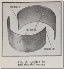
Each half of a shell type bearing is usually provided with a locking lip or tang at one end, Fig. 56. The lip fits into a mating notch in the connecting rod and thus aligns the bearing. The same construction is used for main bearings.
For main and rod bearings, there are two alloys in common use in addition to babbitt, namely copper-lead and cadmium. In recent years alumi num faced bearings have been used in some engines. In all cases the bearing metal is bonded to a steel back. The copper-lead alloy contains 60% copper and 25% lead or even higher percent ages of one or the other metal. Cadmium bearings usually contain more than 98% of cadmium.Bronze is an alloy which is principally composed of copper and tin. Bronze bushings are used for piston pins.
Camshaft bearings are made of a variety of alloys such as bronze, bronze-backed babbitt lined, steel-backed babbitt-lined. These bearings may be made in one piece like a bushing or they may be made of the precision type in which case they are split in two halves.
On most engines in use today there are three main bearings for four cylinders, seven main bear ings for in-line sixes, and five main bearings for V8’s.
CRANKSHAFT COUNTERWEIGHTS
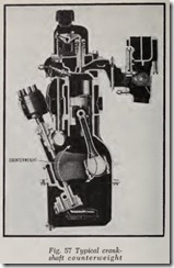
Most modern crankshafts are equipped with counterweights, Fig. 57. These weights are an integral part of the crankshaft. Their principal purpose is to counterbalance the weight of the crankpins and their cheeks. In other words, the centrifugal force of the latter is counterbalanced by the former.
In further explanation it should be noted that in spite of the fact that a crankshaft is a relatively stiff or rigid piece of steel two or three inches in diameter, nevertheless the weight of the crankpins and their cheeks (or throws) produces such a high centrifugal force at high speeds that a crank shaft without counterweights might be bent suffi ciently to cause excessive wear of the main bear ings. Therefore the purpose of the counterweigh ts is to counteract this bending. Also the elimination of bending makes a smoother and quieter running engine because a crankshaft which bends in its bearings also bends the crankcase, thus increasing noise and vibration.
VIBRATION DAMPERS
Crankshafts are subject to torsional vibration. This vibration is a very rapid circumferential winding and unwinding of the front end of the crankshaft. Torsional vibration occurs at certain definite speeds which vary with different crank shafts. In a typical case, obj ectionabl e torsional vibration might occur at 1200, 1600 and 2400 rpm, the intensity being approximately twi ce as much at 1600 as at 1200; likewise twice as m u ch a t 2400 as at 1600.
Torsional vibration is caused by the steadily recurring impulses of the pistons which cause th e front end of the crankshaft to wind and unwind at a very rapid rate. Torsiona l vibration is sup pressed by a vibration damper (also called har monic balancer). The damper consists of a small flywheel installed on the front end of the crank shaft, usually rotated by the cranksha ft through rubber bushings, Fig. 58. As soon as the front end of the crankshaft starts vibrating, the flywh eel in its rubber bushings starts vibrating opposit ely, thus bucking and discouraging the build up of vibration in the crankshaft. Because of th e ener getic opposition of this damper flywheel the torsional vibrations in the crankshaft never become powerful enough to be noticed. The damper is usually incorporated in the crankshaft pulley.Torsional vibration is considered negligible in American four-cylinder engines as well as in some V8’s, in which case no vibration damper is re quired, nor is one always needed in small six cylinder engines with short crankshafts. But larger in-line six and eight cylind er engines invariably have vibration dampers.
FLYWHEEL
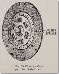
The flywheel is slightly affected by torsional vibration, fluctuating slightly but rapidly back and forth while the crankshaft rotates. This vibration may produce an objectionable screech somewhere between the clutch driven disc and the rear wheels. In order to nullify the effect of this vibra tion it is customary t6 cushion the hub of the clutch disc with springs, Fig..59. The clutch disc drives the hub through these springs . At the same time, friction material clamped between the disc and the hub prevents the hub from picking up the torsional vibration of the flywheel. This type of hub is used on practically all cars with manual shift transmissions.
Review Questions
1. Name the four strokes comprising the operating cycle of an automobile engine. . . .. .. . .
2. When does a four-stroke cycle engine operate as an air pump? …………… … . . · . . .
3. Why does a small amount of exhaust gas always remain in the combustion chamber after the exhaust stroke is completed? …………………………………… · ·· ·· ·· ·
4. How is power in an automobile engine produced? …………………………… .
5. How does the speed of the combustion process in an automobile engine compare with the speed of exploding dynamite? …………………………………………… .
6. What are the basic ingredients of the combustible mixture in an automobile engine? … .
7. Name the two parts that form the combustion chamber. . …………………….. .
8. How is steam formed during the combustion process? …………………………. .
9. The mixture of what two elements produces carbon dioxide? ………………….. .
10. How is carbon monoxide formed? ……………………………………….. .
11. Why is it incorrect to say that the mixture is sucked into the engine? …………….. . 12. Explain the purpose of the manifold heater. . ………………………………. .
13. On cars with dual exhaust systems, explain why the exhaust gas comes out of only one mufHer tail pipe when the engine is cold? ………………………………….. .
14. What is valve overlap? ………………………………………………… .
15. What are the advantages of delaying the closing of intake valves? ………………. .
16. Early intake valve closing is favorable to power at what speeds? ………………… .
17. Later intake valve closing assists power production at what speeds? ….. . ……….. .
18. What is the piston displacement of a six-cylinder engine having a bore and stroke of 3″ X 4″? …. …. …
19. What sort of horsepow er is brake horsepower? Taxable horsepower? …………….. .
20. Defin e compression ratio. . .. ……………………………….
21. What causes detonation? Spark knock? Pre-ignition? …………………………. .
22. How does the cooling system control the temperature of pistons, rings and valves? ….. .
23. How does the Corvair cylinder numbering system differ from those of other American engines? …………. . ………. …
24. Define the meaning of “Firing Order.” .. …………… . ……………………. .
25. Explain how piston travel is changed to rotary motion at the crankshaft.
26. Why are no separate main bearing caps required on the Corvair engin e? . . . . . . . . . . . . . .
27. Why is an L-head engine so called? . . . . . . . . . . . . . . . . . . . . . . . . . . . . . . . . . . . . . . . . . . . . . .
28. Where are the valves located in an F-hea d en gine? . . . . . . . . . . . . . . . . . . . . . . . . . . . . . . . . . .
29. What is the function of a cylinder head gasket? . . . . . . . . . . . . . . . . . . . . . . . . . . . . . . . . . . . .
30. How do barrel type and mushroom type tappets differ? . . . . . . . . . . . . . . . . . . . . . . . . . . . . . .
31. What is the advantage of a 30° valve seat; 45° valve seat? . . . . . . . . . . . . . . . . . . . . . . . . . . . .
32. In a four-cycle engine, why does the camshaft operate at one half the crankshaft speed?
33. Why is it desirable to make valves with head diameters as large as possible in an engine?
34. Name the £ve different surfaces on a cam. . . . . . . . . . . . . . . . . . . . . . . . . . . . . . . . . . . . . . . . .
35. Why is it necessary to suppress valve surge? . . . . . . . . . . . . . . . . . . . . . . . . . . . . . . . . . . . . . .
36. How is cylinder head and block distortion kept to a minimum when cylinder head bolts are tightened? . . . . . . . . . . . . . . . . . .
37. Why is it necessary to have a little clearance between piston and cylinder bore? . . . . . . . .
38. Name two common types of aluminum pistons.
39. Name three reasons why a cam-ground (oval) piston works successfully. . . . . . . . . . . . . . .
40. What are the advantages of coated pistons? . . . . . . . . . . . . . . . . . . . . . . . . . . . . . . . . . . . . . . . .
41. Why should piston ring gaps be staggered around the piston? . . . . . . . . . . . . . . . . . . . . . . . .
42. Why is it important to have the drain holes in piston ring grooves clean and open? . . . .
43. Describe four ways a connecting rod may be attached to a piston. . . . . . . . . . . . . . . . . . . . .
44. What is the difference between a main bearing and a main bearing journal? . . . . . . . . . . . .
45. Why is it necessary to allow for a running clearance when £tting main or rod bearings?
46. How many main bearings would you expect to £nd in a modem V8 engine? . . . . . . . . . . . .
47. What would happen to the main bearings in an engine without counterweights on the crankshaft? . . . . . . . . . . . . . . . . . . .
48. Describe torsional vibration in a crankshaft.
49. Explain how a vibration damper opposes torsional vibration? . . . . . . . . . . . . . . . . . . . . . . . .
50. What would result if there were no cushion springs in a clutch driven plate? . . . . . . . . . . . .
![Fig. 43 Unsymmetrical_thumb[1] Fig. 43 Unsymmetrical_thumb[1]](http://machineryequipmentonline.com/electric-equipment/wp-content/uploads/2020/06/Fig.-43-Unsymmetrical_thumb1_thumb.jpg)
![Fig. 47 How piston presses_thumb[1] Fig. 47 How piston presses_thumb[1]](http://machineryequipmentonline.com/electric-equipment/wp-content/uploads/2020/06/Fig.-47-How-piston-presses_thumb1_thumb.jpg)
