Overload Contacts
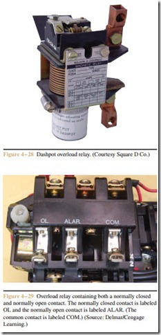
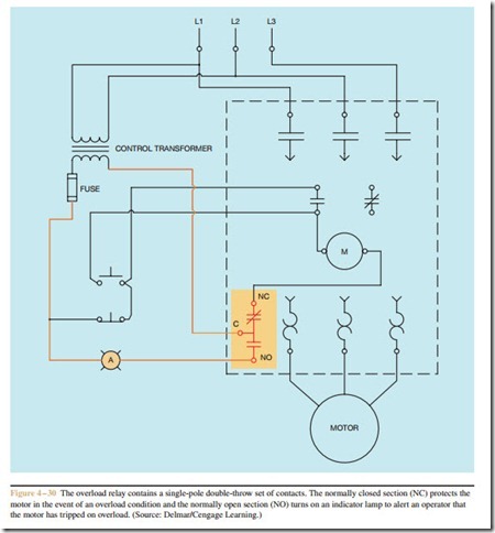
Although all overload relays contain a set of normally closed contacts, some manufacturers also add a set of normally open contacts as well. These two sets of contacts are either in the form of a single-pole double-throw switch or of two separate contacts. The single-pole double-throw switch arrangement will contain a common terminal (C), a normally closed terminal (NC), and a normally open terminal (NO) (Figure 4 – 29). There are several reasons for adding the normally open set of contacts. The starter shown in Figure 4 – 30 uses the normally closed section to disconnect the motor starter in the event of an overload, and uses the normally open
section to turn on an indicator light to inform an opera- tor that the overload has tripped.
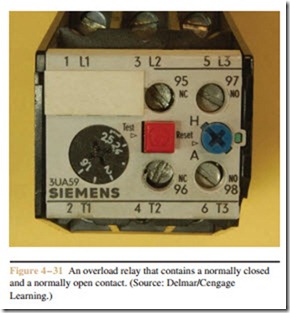
The overload relay shown in Figure 4 – 31 contains two separate sets of contacts, one normally open and the other normally closed. Another common use for the normally open set of contacts on an overload relay is to provide an input signal to a programmable logic controller (PLC). If the overload trips, the normally closed set of contacts will open and disconnect the starter coil from the line. The normally open set of contacts
will close and provide a signal to the input of the PLC (Figure 4 – 32). Notice that two interposing relays, CR1 and CR2, are used to separate the PLC and the motor starter. This is often done for safety reasons. The control relays prevent more than one source of power from entering the starter or PLC. Note that the starter and PLC each have a separate power source. If the power were disconnected from the starter during service or re- pair, it could cause an injury if the power from the PLC were connected to any part of the starter.


