DC Motors
Direct-current motors are classified according to the type of winding employed, as:
1. Series-wound,
2. Shunt-wound,
3. Compound-wound.
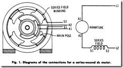
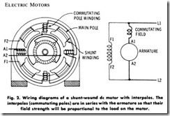
The series-wound motor (Fig. 1) is one in which the field coils and armature are connected in series, and the entire current flows through the field coils. The shunt-wound motor (Fig. 2) derives its name from the fact that the field coils and the armature are connected in shunt (parallel), and because of this, the field current is only a small portion of the total or line current.
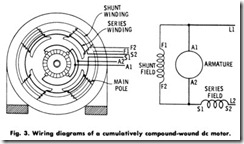
The compound-wound motor (Fig. 3) incorporates both the series wound and the shunt- wound windings. In other words, it has both the series and the shunt windings previously illustrated.
CONSTRUCTION
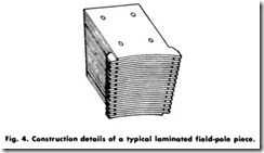
All de motors, regardless of size, have a stationary field member (usually called a frame or yoke) and a rotating armature member. The frame, which is made of cast or fabricated steel, serves as a means of support for the motor and forms a part of the magnetic circuit connecting the field poles and commutating poles. The field poles upon which the field coils are wound are made of cast steel, forged steel, or steel laminations. When cast or forged steel is used, the cores are usually made with a circular cross section. Laminated poles (Fig. 4) are most commonly used (except for very small motors), have a rectangular cross section, and are fastened to the frame by bolts.
The armature is made of machine- wound coils embedded in parallel slots on the surface of the armature core. The core is made of thin wrought-iron or mild-steel stampings of from 18 to 25 mils in thickness.
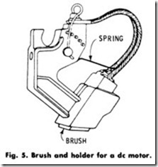
The brushes are constructed as a means of carrying the current from the external to the internal circuit. They are usually made of carbon and are carried in brush holders (Fig. 5) which are mounted on brush-holder studs or brackets.
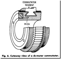
The commutator (Fig. 6) is built up of segments of hard-drawn copper insulated from the supporting rings by “built-up” mica to form a cylinder. These segments are tightly clamped together by means of a heavy external ring. In order to improve commutation, modern motors are equipped with auxiliary poles, variously termed interpoles or commutating poles. These are small auxiliary poles placed between the regular field poles. Their purpose is to assist commutation and prevent sparking at the brushes for different loads.
OPERATING CHARACTERISTICS
Series Motors
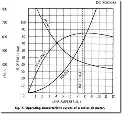
The load characteristic curves of a series motor are given in Fig. 7. A study of the current-torque curves indicates that the torque varies approximately as the square of the armature current. From this, it follows that this type of motor is suitable in load applications where it is necessary to supply a large torque with a moderate increase in current, such as in traction work, crane operation, etc.
The speed of a series motor, as indicated, varies greatly with the change in load. Because of this speed characteristic, and the resultant possibility of dangerously high speed at light loads, this motor is not suitable for belt drive or for use on any load where the torque might drop below 15% of full-load torque.
Shunt Motors
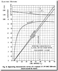
From the characteristic curves of a shunt motor (Fig. 8) it will be noticed that this motor will run at very nearly the same speed at any load within its capacity, and will not slow very much even when greatly overloaded. There is but a slight drop in speed from no load to full load. This drop may vary from 5 to 15% of the full-load speed, being dependent on saturation, armature reaction, and brush position.
Because of commutation limitations, shunt motors in integral horse power sizes are not suitable for across-the-line starting. Shunt motors designed for operation over a given speed range by field control are not technically shunt motors, in that a stabilizing series field is added to assure stable speed· under weak field conditions. When this winding is included, the possibility of armature reaction demagnetizing the weak ened shunt field with a change in load is eliminated. Shunt motors without speed control are used to drive machinery that is designed to run continuously at a constant speed.
Compound Motors
The addition of a cumulative series field winding to the shunt field produces a compound motor. The addition of this series-field winding gives the motor a characteristic which is a combination of the series and shunt motor.
The speed changes with the load, but it does not change as much as in a series motor and it usually changes a great deal more than in a shunt motor. Like the series motor, the compound motor has excellent characteristics for starting heavy loads and yet is in no danger of ‘running away” at light loads when used without a speed controller.
Compound motors are used for loads requiring high starting torque, or for loads subject to torque pulsations. They are not practical for applications requiring adjustable speed by field control. With a weak ened shunt field, the series-field flux becomes a greater portion of the total flux; hence the changes in load may produce unstable speeds.
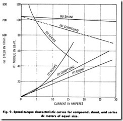
Compound motors are commonly employed for elevators, air com pressors, ice machines, certain kinds of hoisting and conveying ma chinery, printing presses, paper cutters, pumps, and other machinery where the load fluctuates suddenly or periodically, and where constant speed is not essential. They are usually designed so that there will be a drop in speed of about 20% between no load and full load. Compound motors may be wound for greater or less speed change to meet special conditions and are usually wired for across-the-line starting in sizes up to 5 hp (3.73 kW). Comparisons of the speed-torque characteristic curves of series, shunt, and compound de motors are given in Fig. 9.
SPEED CONTROL
The factors which determine the speed of a motor are the voltage across its armature and the strength of the field. If the voltage supplied to the armature is reduced to one-half its original value, the speed of the motor will be reduced in the same proportion. Similarly, if the voltage across the armature is doubled, the speed will be doubled, provided the field strength remains the same. In the same manner, if the magnetic field is weakened, the motor speed will increase, and if the field is strengthened, the motor speed will be reduced. There are four principal methods whereby the speed of a de motor can be regulated. They are:
1. Shunt-field control,
2. Armature-resistance control,
3. Variable- voltage control,
4. Multivoltage control.
Shunt-Field Control
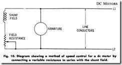
It has previously been pointed out that weakening the field increases the speed of a motor, and strengthening the field decreases the speed. This method of varying the speed can be accomplished by means of a variable resistance inserted in series with the shunt field, and is the most commonly used as a means of speed control for de motors. By this method, the speed of a shunt motor may be varied from normal to four times normal, depending largely upon the mechanical construction of the motor.
It is generally impractical to build adjustable-speed motors for a range exceeding four-to-one, because the shunt field becomes so weak ened that the characteristics of the motor assume more the shape of a heavily compounded motor curve than shunt curves. A schematic diagram showing this method of speed control is shown in Fig. 10.
The variable field resistance may be a simple field rheostat or it may be combined with a starting rheostat. Shunt-motor speed control by means of a variation in field resistance is most satisfactory and efficient. The wattage loss (f R) in the field-circuit resistance in small since the field current is small compared to the armature current.
This method of speed control is also used for compound motors, although for any speed setting, there is some variation in the speed with load, in contrast to the shunt motor, where the speed is but slightly affected by the load.
For speed control of series motors, this method is often applied, although in a modified form. Here, it consists in shunting part of the current arount the field coils, thus weakening the magnetic field and increasing the speed of the motor.
Armature-Resistance Control
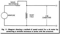
The speed of a de motor may be decreased by inserting a resistance in series with its armature, as shown in Fig. 11. The speed at full load may be decreased to any desired value, depending on the amount of this resistance. With this method, the armature voltage drops as the current passes through the series resistance, and the remaining voltage applied to the armature is lower than the line voltage. Thus, the speed is reduced in direct proportion to this voltage drop at the armature terminals. For example, if at full load an amount of resistance is inserted so that
one-half of the voltage is consumed in the resistance, the motor speed will be reduced to one-half.
In the case of a 220-volt motor with an armature current of, say, 50 amperes and a series resistance of 2 ohms inserted in the armature circuit, the voltage drop will be 2 x 50, or 100 volts. In this case, 120 volts will be applied to the armature and the resulting speed reduction will be 120/220, or 55% of normal speed. The wattage loss (I2R) in this case will be 502 x 2, or 5000 watts.
If, on the other hand, the armature current were only 25 amperes and all other factors remain the same, then the voltage drop would be 25 x 2, or 50 volts. The voltage applied to the armature would then be 220 – 50, or 170 volts, and the speed of the motor would be 170/220, or 77% of normal. The wattage loss in this latter case would be 1250.
Thus, it will readily be observed from the examples shown that this method of speed control is inefficient and costly, since a large propro tion of the energy to the motor is dissipated in heat. It is sometimes difficult to dissipate this heat, and the regulation is very poor.
Standard speed controllers are commonly made to reduce the speed 50% when full-load current is flowing through the armature. If only half the full-load current is flowing through the armature, the speed will be reduced only about 25%
Variable-Voltage Control
This system of speed control requires a generator for each motor, the motor field being maintained constant while its armature voltage is varied by varying the generator field strength. This method gives a large speed range with any desired number of speed points. It is essentially a constant-torque system, because the horsepower delivered by the motor decreases with a decrease in applied voltage and a corresponding decrease in speed.
This particular system has a further advantage that can be used to provide excellent starting characteristics by bringing the generator voltage gradually up from zero, starting and bringing the motor up to speed with a comparatively slowly increasing voltage. Because of the excellent starting characteristics, this system is used largely for modern high-speed elevators, and on account of the combination of excellent starting characteristics and the wide speed range available, it is used to some extent for reversing-planer installations. It is not applied to any great extent, generally on account of the expense of the generating equipment.
Multivoltage Control
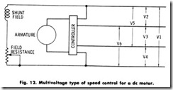
The multivoltage system consists of a generating plant or system so arranged that a number of different voltages may be applied to the armature of a motor whose field is connected across a constant voltage, as illustrated in Fig. 12. Six different voltages may be obtained with this particular circuit. By means of a suitable controller, any one of the voltages may be supplied to the motor armature terminals, while the shunt field is connected directly to the outside line wires. Since the speed of the motor is directly proportional to the voltage impressed on the armature terminals, a variety of motor speeds may thus be obtained.
Because of the high cost of the power-generating machinery and the current -carrying conductors, however, this type of motor speed control is seldom used. With modern commutating-pole motors, a more eco nomical speed range may be obtained by the common field-resistance control previously described.
Ward-Leonard Speed Control
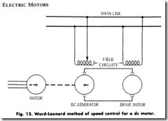
This system of speed control (Fig. 13) utilizes a motor-generator setcomprising a de generator supplying current to a shunt motor connected as indicated. Here, the field circuit of the generator is supplied from the main circuit and has a field rheostat with sufficient resistance to vary the field current from its full value to nearly zero. The drive motor, whose speed it is desired to regulate, has its armature connected to the variable- voltage generator, while its field current is supplied from the main line. With this arrangement, any speed of the drive motor, from full value to nearly zero, may be obtained by adjustment of the generator field current.
Due to the cost of the machinery involved (three full-sized machines required instead of one), this method is used only when the required range and precision of speed adjustment cannot be obtained by a more economical method. It is used to some extent in the operation of large printing presses, in gun turrets aboard battleships, etc.
Special Control Methods
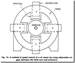
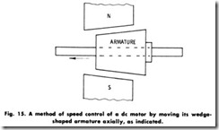
Another method of motor speed control is obtained by changing the air gap (field flux) between the poles and the motor armature (Fig. 14). In some motors of this type, the field cores are geared together at their outer ends so that they may all be moved simultaneously in or out by means of a gear mechanism and handwheel. In others, the armature and the field poles are slightly tapered (Fig. 15), and a gear mechanism shifts the armature along the shaft. In both methods, the speed is varied by adjusting the air gap. The speed is increased by lengthening the air gap (weakening the field) and is decreased by shortening the gap (strengthening the field). This method (which is but another adaptation of speed control by field manipulation) is seldom used, mainly because of the high construction cost.
Dynamic Braking
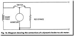
With reference to Fig. 16, dynamic braking of a shunt motor is accomplished by inserting a resistance in parallel with the armature, as shown. When dynamic braking is desired, the armature is disconnected and immediately connected to the OFF or BRAKE position, placing the resistance bank directly across the armature terminals. The rotation of the armature under the influence of the excited shunt field causes a voltage to be generated, sending current through the resistance. As a result, the motor functions as a loaded generator and develops a retarding torque which rapidly stops the motor
