The BEM method
All the theory and important definitions to determine the force components on a blade element have been introduced and a first trial approach has been given to finding a solution in Example 10.5. The various steps of the classical BEM model from Glauert are formalized in Table 10.1 as an algorithm for evaluating a and a0 for each elementary control volume.
Spanwise variation of parameters
Along the blade span there is a significant variation in the blade-pitch angle β, which is strongly linked to the value of J and to a lesser extent to the values of the lift coefficient CL and the blade chord l. The ways both CL and l vary with radius are at the discretion of the turbine designer. In the previous example, the value of the pitch angle was specified and the lift coefficient was derived (together with other factors) from it. We can likewise specify the lift coefficient, keeping the incidence below the angle of stall and from it determine the angle of pitch. This procedure will be used in the next example to obtain the spanwise variation of β for the turbine blade. It is certainly true that for optimum performance the blade must be twisted along its length with the result that, near the root, there is a large pitch angle. The blade-pitch angle will decrease with increasing radius so that, near the tip, it is close to zero and may even become slightly negative. The blade chord in the following examples has been kept constant to limit the number of choices. Of course, most turbines in operation have tapered blades whose design features depend upon blade strength as well as economic and aesthetic considerations.
EXAMPLE 10.6
A three-bladed HAWT with a 30 m tip diameter is to be designed to operate with a constant lift coefficient CL 5 0.8 along the span, with a tip-speed ratio J 5 5.0. Assuming a constant chord of 1.0 m, determine, using an iterative method of calculation, the variation along the span (0.2 # r/R # 1.0) of the flow induction factors a and a0 and the pitch angle β.
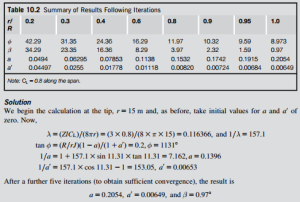
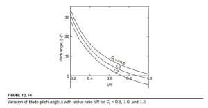
The results of the computations along the complete span (0.2 # r/R # 1.0) for a and a0 are shown in Table 10.2. It is very evident that the parameter a varies markedly with radius, unlike the actuator disc application where a was constant. The spanwise variation of the pitch angle β for CL 5 0.8 (as well as for CL 5 1.0 and 1.2 for comparison) is shown in Figure 10.14. The large variation of β along the span is not surprising and is linked to the choice of the value of J, the tip-speed ratio. The choice of inner radius ratio r/R 5 0.2 was arbitrary. However, the contribution to the power developed from choosing an even smaller radius would have been negligible.
Evaluating the torque and axial force
The incremental axial force can be derived from Eqs (10.29) and (10.19) in the form
EXAMPLE 10.7
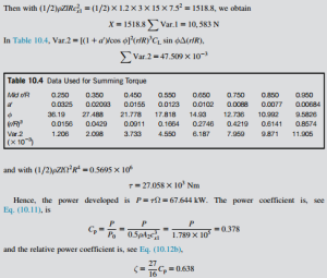
Determine the total axial force, the torque, the power, and the power coefficient of the wind turbine described in Example 10.5. Assume that cx1 5 7.5 m/s and that the air density ρ 5 1.2 kg/m3.
Solution
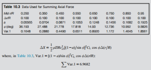
Evaluating the elements of axial force ΔX having previously determined the mid-ordinate values of a, a0, and φ to gain greater accuracy (the relevant data is shown in Table 10.3):
EXAMPLE 10.8
The relationship between actuator disc theory and blade element theory can be more firmly established by evaluating the power again, this time using the actuator disc equations.
Solution
To do this we need to determine the equivalent constant value for a. From Eq. (10.13),
and this agrees fairly well with the value obtained in Example 10.8.
Note: The lift coefficient used in this example, admittedly modest, was selected purely to illustrate the method of calculation. For an initial design, the equations just developed would suffice but some further refinements can be added. An important refinement concerns the Prandtl correction for the number of blades.
Correcting for a finite number of blades
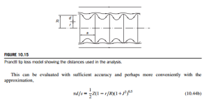
So far, the analysis has ignored the effect of having a finite number of blades. The fact is that at a fixed point the flow fluctuates as a blade passes by. The induced velocities at the point are not con- stant with time. The overall effect is to reduce the net momentum exchange and the net power of the turbine. Some modification of the analysis is needed and this is done by applying a blade tip correction factor. Several solutions are available: (i) an exact one due to Goldstein (1929), represented by an infinite series of modified Bessel functions, and (ii) a closed form approximation due to Prandtl and Tietjens (1957). Both methods give similar results and Prandtl’s method is the one usually preferred.
Prandtl’s correction factor
The mathematical details of some parts of Prandtl’s analysis are beyond the scope of this book, but the result for F is usually expressed as
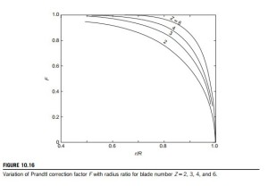
The circulation at the blade tips reduces to zero because of the vorticity shed from it, in the same way as at the tip of an aircraft wing. These expressions ensure that F becomes zero when r 5 R but rapidly increases toward unity with decreasing radius.
The variation of F 5 F(r/R) is shown in Figure 10.16 for J 5 5 and Z 5 2, 3, 4, and 6. It will be clear from the graph and the preceding equations that the greater the pitch s and the smaller the number of blades Z, the bigger will be the variation of F (from unity) at any radius ratio. In other words, the amplitude of the velocity fluctuations will be increased.
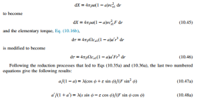
Prandtl’s tip correction factor is applied directly to each blade element, modifying the elementary axial force, obtained from Eq. (10.13),
The application of the Prandtl tip correction factor to the elementary axial force and elementary torque equations has some important implications concerning the overall flow and the interference factors. The basic meaning of Eq. (10.45) is
i.e., the average axial induction factor in the far wake is 2aF when the correction factor is applied as opposed to 2a when it is not. Note also that, in the plane of the disc (or the blades), the average induction factor is aF, and that the axial velocity becomes
From this, we see that at the tips of the blades cx2 5 cx1, because F is zero at that radius.
Note: It was explained earlier that the limit of application of the theory occurs when a-0.5, i.e., cx2 5 cx1(1 2 2a), and, as the earlier calculations have shown, a is usually greatest toward the blade tip. However, with the application of the tip correction factor F, the limit state becomes aF 5 0.5. As F progressively reduces to zero as the blade tip is approached, the operational result gives, in effect, some additional leeway in the convergence of the iterative procedure discussed earlier.
Performance calculations with tip correction included
In accordance with the previous approximation (to reduce the amount of work needed), ε is ascribed the value zero, simplifying the preceding equations for determining a and a0 to
When using the BEM method, an extra step is required in Table 10.1, between steps 1 and 2, to alculate F, and it is necessary to calculate a new value of CL for each iteration that, consequently, changes the value of the blade loading coefficient λ as the calculation progresses.
EXAMPLE 10.9
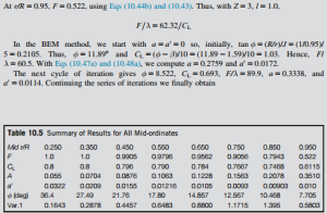
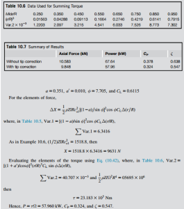
This example repeats the calculations of Example 10.8 using the same blade specification (i.e., the pitch angle β 5 β(r)) but now it includes the Prandtl correction factor. The results of the iterations to determine a, a0, φ, and CL and used as data for the summations are shown in Table 10.5. The details of the calculation for one mid-ordinate radius (r/R 5 0.95) are shown first to clarify the process.
Solution
These calculations, summarized in Table 10.7, demonstrate that quite substantial reductions occur in both the axial force and the power output as a result of including the Prandtl tip loss correction factor.

