Oil-Fired Water Heaters
Most of the oil-fired heaters used in residences and small buildings are of the external, or floating, tank design (see Figure 4-56). The products of the combustion process pass upward through the flue passages located between the suspended hot-water storage tank and the outer walls of the water heater. Multiflue and internal flue oil-fired water heaters, though less common, are also used (see Figure 4-57).
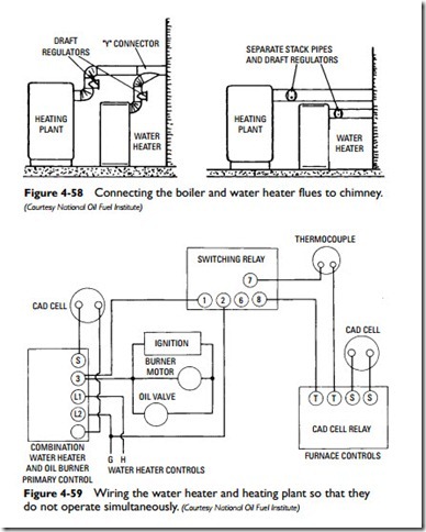
As with gas-fired water heaters, an oil heater must have an adequate draft for proper combustion. Sometimes it is necessary to vent two oil-fired appliances (for example, furnace and water heater) into the same flue. When this situation occurs, the two can be connected to the flue either with a “Y” connection or in such a way that both feed directly into the flue (see Figure 4-58). When two oil- fired appliances, such as a furnace and a water heater, are connected to a single vent, the controls can be wired to prevent simultaneous operations and give priority to the water heater (see Figure 4-59).
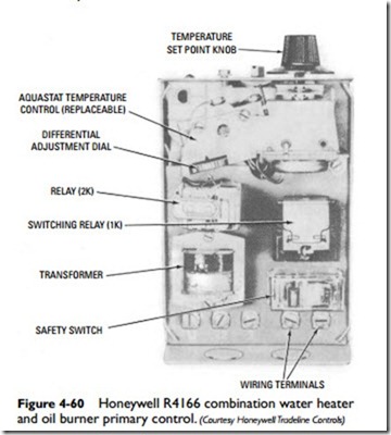
Oil-fired water heater controls are similar to those used to control hot- water space-heating boilers. They are also designed to regulate the temperature of the water in the water heater storage tank. For example, the primary control shown in Figures 4-60 and 4-61 is used in conjunction with an immersion aquastat and a remote sensor (cadmium detection cell) to simultaneously regulate the water temperature and pro- vide oil burner control. Both oil burner malfunctions and water temperatures that fall outside the rated temperature range of the heater will cause the primary control to start or stop the oil burner as conditions require.
Pressure and temperature relief valves are vital for the protection of the hot-water storage tank. These valves are described elsewhere in this chapter (see Relief Valves).
When adjusting an oil-fired water heater, always adjust for a smoke-free fire first, and then make the necessary adjustment for efficient operation.


