Fresh Air Requirements
Table 6-1 lists necessary air changes for various rooms and buildings and thus offers a guide as to the amount of air required for efficient ventilation. This information should be used in connection with the ventilator capacity tables in the proper selection of the number and size of units required.
Where two figures are given for one type of building, use the smaller figure when conditions are normal and the larger figure when they are abnormal. Certain buildings are better figured on a cfm (cubic feet per minute) per occupant basis. Their requirements are given in this manner.
Ventilator Bases
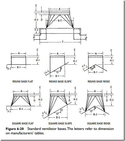
The ventilator base is the connection between the other elements of the ventilator and the roof. It must be designed so as to fit the contour of the roof and the opening on which it is mounted. Its design and construction is important, particularly in ventilator sizes and types where weight and wind resistance are high. Ventilator manufacturers provide a wide variety of different ventilator base sizes. In their literature, illustrated base designs (see Figure 6-20) are cross-referenced with dimensional tables for the convenience of the buyer.
Gauges of metal are used that ensure rigidity and strength. Reinforcement is added where needed. Flashing flanges are amply wide to ensure rigid, weather-tight joints that will not leak when properly fastened and flashed to the roof. All seams are well riveted, soldered, or doped (the latter in asbestos-protected steel) to ensure storm-tight joints. All connections to the roof and to the next adjacent ventilator unit (the head in a gravity unit or the fan in a fan unit) are designed for 75-mph wind velocity as standard or 100 mph optional.
Since the outside sheet-metal surfaces of ventilators are exposed to atmospheric temperatures and the inside surfaces to room temperature, there is frequently a tendency for condensation to form on the
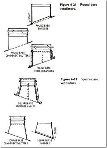
inside surfaces. In order to minimize the possibility of condensation drip into the ventilated space, condensation gutters may be provided to drain the water to the outside of the ventilator. These condensation gutters are usually located at the extreme lower edge of the base where as little water as possible can get past them.
The round ventilator bases in Figure 6-21 are standard but can be omitted if a duct is to be fitted into the lower end of the base with which the gutter would interfere. Examples of spare bases are shown in Figure 6-22, but these are special. In either type, drains
from the gutter to the roof are ample for drainage and to prevent clogging.
In ventilator sizes and types where weights are not great, bases are lapped into the next adjacent unit above. In order to properly position the units and to add stiffness, a wedge is provided in the base against which the next adjacent unit seats.
Angle Rings
In larger ventilator sizes where added strength, rigidity, and ease of erection are important, angle rings have been used to connect the base to the next adjacent unit (ventilator head, fan section, or stack).
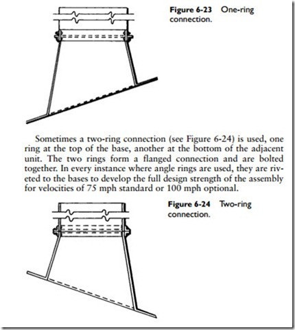
In certain instances a one-ring connection (see Figure 6-23) is used with the upper edge of the base lapping into the next adjacent unit, which rests upon the angle ring. The bolted connection is made through the sheet-metal lap. The lap connection is ample to ensure proper bearing for connection screws or bolts. When angle rings are provided, wedges are not used.
Stiffener Angles
Stiffener angles are provided in conjunction with angle rings in certain applications where the sheet metal needs reinforcing. These lie vertically along the outside of the base surface at quarter points and extend from the angle ring at the top to the outer edge of the roof flange at the bottom. They are riveted to the base sheet metal and welded to the angle ring. Bolted connections through portions of the stiffener that lie along the roof flange to the curb or framing members below provide rigid structural members through which load is carried to the roof structure.
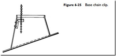
Where applicable and with certain types of dampers, a small clip can be supplied and riveted to the base (see Figure 6-25). The damper chain drops through this clip and can be locked at any point to properly position the damper. This clip is useful when the damper is to be operated from a point directly below the ventilator since it avoids the use of pulleys and complicated chain arrangements.


