USING TRANSFORMER FORMULAS
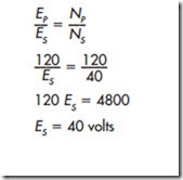
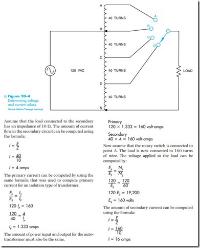
The values of voltage and current for autotransformers can also be determined by using standard transformer formulas. The primary winding of the transformer shown in Figure 20–4 is between points B and N, and has a voltage of 120 volts applied to it. If the turns of wire are counted between points B and N, it can be seen that there are 120 turns of wire. Now assume that the selector switch is set to point D. The load is now connected between points D and N. The secondary of this transformer contains 40 turns of wire. If the amount of voltage applied to the load is to be computed, the following formula can be used.
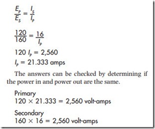
The primary current can be computed using the formula:
Related posts:
Air-Conditioning Equipment:Troubleshooting Electrical Components
Motors:Three-Phase Motor Principles
Central Plants:Chillers
MOTORS:STARTING
Service valves and gauges:Purging hoses and manifold
Steam and Hydronic Line Controls:Pipeline Strainers
Drive motors:Earthing
Problems on hydraulic turbines.
Introduction, Basic Principles:Small stage or poly tropic efficiency


