Computational through-flow methods
Actuator disc theory gives some understanding of the meridional through-flow in turbomachines of simple geometry and flow conditions, but its application to design and analysis is now quite limited. Numerous computational methods have evolved for predicting the meridional flow field for single-stage and multistage turbomachines with nonaxial annulus lines, compressible flow, and blade losses. These are known as through-flow methods and are discussed below.
In any through-flow method, the equations of motion to be solved are simplified. First, the flow is taken to be steady in both the absolute and relative frames of reference. Second, the flow is assumed to be axisymmetric. Outside of the blade rows, the effects of wakes from the upstream blade row are “mixed out” so as to give uniform circumferential conditions. Within the blade rows, the effects of the blades themselves are modeled by passage-averaged body forces and loss coefficients. Clearly, with these major assumptions, solutions from through-flow methods are only approximations to the real flow but, if used appropriately, they can accurately reproduce the meridional variations.
Three techniques for solving through-flow problems are 1. Stream function methods, in which a stream function is employed as the primary variable. This approach has the advantage of simplifying the numerics by satisfying the continuity equation via the boundary conditions of the stream function at the hub and casing. However, it fails when the flow becomes transonic.
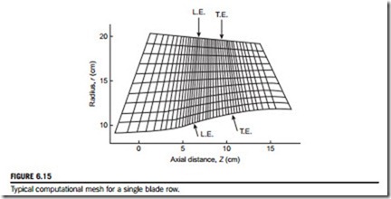
2. Matrix through-flow or finite difference solutions (Marsh, 1968), in which computations of the radial equilibrium flow field are made at a number of locations within each blade row as well as at the leading and trailing edges and outside of the blade row. An illustration of a typical computing mesh for a single blade row taken from Macchi (1985) is shown in Figure 6.15.
3. Time-marching solutions of the streamline curvature equation (Denton, 1985), in which the computation starts from some assumed flow field and the governing equations are marched forward with time. The method requires a large number of iterations to converge but with modern computers, a solution can be obtained within a matter of seconds.
As stated in Denton and Dawes (1999), the time-marching streamline curvature method remains the dominant numerical scheme because of its simplicity and ability to cope with mixed subsonic
and supersonic flows. However, all three approaches essentially solve the same equations of momentum, energy, continuity, and state, for axisymmetric flow through a turbomachine with varying hub and tip radii.
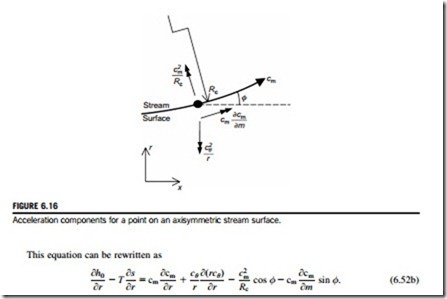
A form of the streamline curvature equation can be derived following the approach presented in Section 6.2. Consider the axisymmetric stream surface and components of acceleration shown in Figure 6.16. In this case, the radial velocity component cannot be neglected and the stagnation enthalpy is written as
The above streamline curvature equation reduces to simple radial equilibrium, Eq. (6.6a), when the radial velocity is zero, since φ-0; Rc-N; cm-cx. The last term on the right-hand side of Eq. (6.52b) represents the radial component of acceleration along the stream surface. The term before this represents the radial component of centripetal acceleration due to meridional curvature. Equation (6.52b) can be solved numerically to find the variations of cθ and cm for given stagnation enthalpy and entropy variations. The solution is combined with the continuity equation to give the velocity levels that match the total mass flow using
Along the streamlines, the tangential velocity, cθ, is found from specified flow angles within blade rows and conservation of angular momentum outside of blade rows, rcθ 5 constant. The Euler equation can be used to find the variation of stagnation enthalpy within blade rows, h0 2 rΩcθ 5 constant. The entropy variation along streamlines is zero outside of blade rows and specified via loss coefficients within the blade rows.
In practice, the solution procedure is further complicated as the directions of the streamlines are not known at the outset and the method must iterate further to find the pitch angle φ at each location, such that the streamline curvature equation balances. In general, initial streamline paths are assumed and these are adjusted as the solution progresses. Figure 6.17 shows an example solution for a single-stage fan rig using a code based on the method by Denton (1978).
Through-flow methods can be applied in design or analysis mode. In analysis mode, the blade row flow angles and loss coefficients are specified and the method determines the velocity field and the spanwise variation of work from the rotor blades. In design mode, the main difference is that the work distribution will be specified and the flow angles and velocity field are determined.


