3D design
Until the 1980s, almost all turbomachinery design could be described as two-dimensional. Following the preliminary design using mean-line analysis, through-flow methods were used to set the spanwise variations and suitable blade sections were specified using cascade test results and blade-to-blade methods. Many turbomachines are still designed in this way without significant consideration of 3D effects. However, the development of 3D computational analysis (see following section) and the improved understanding of 3D flow have enabled more widespread application of 3D design effects. In general, these effects are used to control spanwise variations in the flow field and to reduce secondary flow features.
A detailed explanation of 3D design effects is given in Denton and Xu (1999). In this section, a brief outline is given of how different 3D design changes impact on the flow field and how they can be used to improve a design.
Sweep
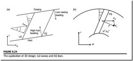
Sweep is where the leading edge (or trailing edge) of a blade row is not perpendicular to the local meridional velocity, as illustrated in Figure 6.24(a). One effect of sweep is to reduce the effective velocity perpendicular to the blade surfaces and thus reduce the local blade loading and surface Mach numbers. This can be thought of in a similar way to the use of swept wings on aircraft to reduce transonic losses from shock waves. The normal velocity is reduced from cm to cm cos λ, where λ is the leading edge sweep angle. For transonic compressor rotors, sweep can be applied to control the shock strength and position. However, this is a complex problem since a shock of a particular strength is required to provide the rotor pressure rise (see Chapter 5) and the position of the shock relative to the blade leading edge influences stability. As found by Wadia, Szucs, and Crall (1997), swept back transonic compressor blades have reduced stability margin because the shock is closer to the leading edge, whereas swept forward blades typically have better stability and they can still be designed to be highly efficient. Modern fan blades for large jet engines typically have a combination of both rearward sweep and forward sweep above mid span.
The effects of sweep near to the endwalls can be determined by considering the fact that pressure gradients perpendicular to the hub and casing must be small (Figure 6.24a). This is true
because there can be no fluid acceleration perpendicular to the endwalls. Given the normal pressure gradient is small, if the blade sweep is such that moving perpendicularly away from the endwall is moving towards a region with low loading (or where there is no blade) then at the endwall the loading must also be low. Conversely, if moving perpendicularly from the endwall is moving rearward in the blade to higher loading, the endwall loading must be high. Blades that are swept forward towards the hub and casing will, therefore, have reduced loading at the leading edge, which can be beneficial in reducing losses.
Lean
Lean is where a blade row is not stacked in the radial direction, as illustrated in Figure 6.24(b). It is more applicable to stators than rotors, since the centrifugal stresses in a rotor will usually demand radial stacking. The effect of lean is to introduce a radial component of the blade force, which acts in addition to the radial pressure gradient and hence modifies the spanwise velocity field. For example, if a stator blade row is leant with the pressure surface towards the hub, the static pressure at the hub will be increased and the meridional velocity will be decreased. This effect has been applied with great success in high aspect ratio steam turbines (Grant and Borthwick, 1987). In these turbines, the hub reaction is very low and decreasing the hub velocity with lean increases this reaction and can significantly improve efficiency.
Endwall profiling
Shaping the hub and casing annulus lines of a turbomachine can be applied to control blade velocity dis- tributions by changing the local meridional curvature and by varying the annulus area. This is, strictly speaking, a two-dimensional effect as it could be predicted by a through-flow method, and the flow field can still be described with axisymmetric stream surfaces. However, endwall profiling in the meridional plane will also affect 3D flow features and it can be applied to reduce secondary flow effects.
It is also possible to use nonaxisymmetric endwall profiling to reduce secondary flow effects. Varying the endwall shape in the tangential direction modifies the endwall pressure distribution, and this can be used to reduce secondary flows or to limit leakage flows between stationary and moving endwalls (Rose, 1994).
Leakage paths, seals, and gaps
In recent years, more attention has been paid to the complete real geometry of turbomachinery, which includes steps and bumps, fillets, seals and gaps. These geometrical imperfections can have significant effects on efficiency, particularly where they influence secondary flows, leakage losses, or flow separations. Many modern 3D computational methods can now include these geometrical features and through examining the predicted flow field, fairly modest changes to the location and shape of the detailed geometry have been proposed that are shown to reduce losses. This is an active field of research that is expected to become of increasing importance now that most other sources of loss in turbomachinery designs have been minimized.
