Open (Atmospheric) Vapor Systems
A vapor system with a return line open to the atmosphere without a check, trap, or other device to prevent the return of air is some- times referred to as an open, or atmospheric, system.
An open vapor system is frequently used when the steam is delivered from its source under high pressure. When this is the case, pressure-reducing valves should be installed in the system to reduce the pressure of the steam to a suitable operating level. An open vapor system is also used when there is no need to return the condensate to the boiler (i.e., when it is wasted within the system). A condensate-return pump should be used when the system design requires the return of the condensate to the boiler.
In an open vapor system, the pressure at the boiler is 1 to 5 oz, or enough to overcome the frictional resistance of the piping
system. The pressure at vent is zero gauge, or atmospheric. In oper- ation, steam is maintained at about 5 oz pressure in the boiler by the action of the automatic damper regulator. The amount of heat desired at the radiators is regulated by the degree of opening of the supply valve. Steam enters at the top of the radiator and pushes out the air through the outlet connection, which is open to the atmosphere. The condensate returns to the boiler by gravity. This system has the advantage of heat adjustment at the radiator, but the devitalizing effect in the air is somewhat greater than in the vacuum systems because the steam entering the radiators is at a higher tem- perature than the steam of lower pressure in the vacuum system. It is, however, simple.
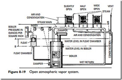
Figure 8-19 illustrates a very simplified, mechanically controlled, vapor steam heating system. Though it does not present the latest practice, it does present control principles very plainly.
The success of a vapor steam heating system depends upon the proper working of the automatic damper regulator in keeping the boiler pressure within proper limits. To accomplish pressure regulation, the dampers are controlled by a float working in a float
chamber in communication with the water space in the boiler, as shown in Figure 8-19.
When the pressure in the boiler is the same as that of the atmosphere (0 psig), the water level in the float chamber (Figure 8-19) is the same as that in the boiler, and the index hand points to zero.
As steam generates, the steam pressure increases and the water level in the boiler is forced downward. The latter action causes the level in the float chamber to rise until the pressure due to the difference AB (Figure 8-19) of water level balances that in the boiler.
The float, in rising, connected as it is by pulleys and chains to the dampers, closes the ashpit damper, thus checking the draft and pre- venting a further increase of steam pressure.
In this system, the steam feed is connected to the top of the radiators and the air and condensation is taken from the bottom because steam is lighter than either air or condensation. Accordingly, when steam is admitted, it floats on top of the air, thus driving the air out through the lower connection.
The chief feature of a vapor system is that the amount of heat given off by each radiator may be regulated by the steam valve. Thus, in Figure 8-19, the valve of radiator C is opened just a little, which will admit only just enough steam to heat a larger portion of the radiator; with the valve wide open on E, the entire radiator is heated.
The kind of radiator used is the downflow type in which steam enters at one end at the top and the air and condensation pass out at the other end at the bottom.
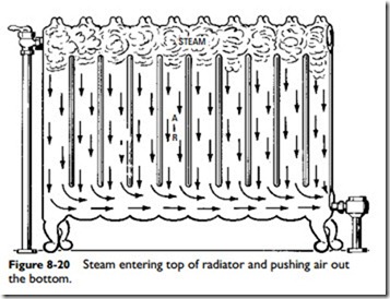
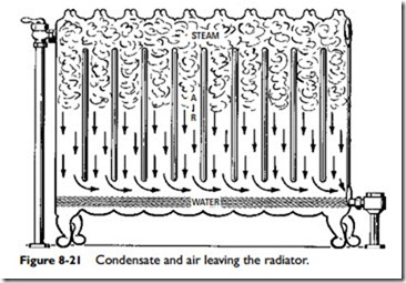
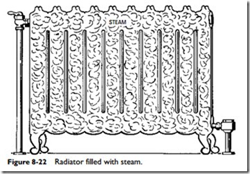
As steam enters a cold radiator, it forces the cool air in the radiator out through the trap into the return piping. The operation of a typical downflow radiator is shown in Figures 8-20 through 8-22. Figure 8-20 shows the steam entering and air passing out through thermostatic retainer valve. Figure 8-21 shows more steam entering and condensate and the balance of the air passing out through the trap, the action progressing until (as in Figure 8-22) the radiator is full of steam.
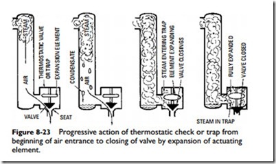
As the radiator warms up, the steam gives off heat and condenses. The condensate, being heavier than steam, falls to the bot- tom of the radiator and flows to the trap through which it passes into the return piping. After the air is forced out, the steam fills the radiator and follows the condensate to the trap. The trap closes when the steam enters it because the steam is hotter than the water. This excess heat expands the valve control element, closing and holding the valve against its seat with a positive pressure, thus pre- venting the steam from flowing into the return piping (Figure 8-23).
The trap closes once the radiator is completely filled with steam, and heat is given off as the steam condenses. The condensate thus formed, which is cooler than the steam, flows in a steady stream to
the trap, which it slightly chills, causing it to open and allowing the condensate to pass out into the return piping (Figure 8-24).
When properly working, the trap adjusts itself to a position corresponding to the temperature of the condensate, just as a
thermometer does to the room temperature, and permits a continuous flow of condensate from the heat-emitting units (Figure 8-25).
