Radiant Heating and Cooling Systems
As you recall from Chapter 3, radiant heat passes in straight lines from a hotter to a cooler body with no affect on the intervening air.
Radiant heaters and coolers are defined as units that achieve more than 50% of their cooling or heating output through radiation (as compared to convection and conduction). We have already discussed radiant floors and ceilings under the heading ‘Panel Heating and Cooling’ in Chapter 8. These panel units operate well below 300°F, and are classified as ‘low temperature’. Radiant floors operate at a relatively low temperature, with a maximum surface temperature, for comfort conditioning, of 84°F.
In this section, we will consider high temperature units that operate at over 300°F, revisit radiant floors and briefly consider radiant ceiling panels.
High Temperature Radiant Units
High temperature, or infrared, units operate at over 300°F. Examples range from units with a hot pipe, to ceramic grids heated to red/white heat by a gas flame, up to electric lamps. These are heaters that are far too hot to get really close to or to touch. There are three main types of high temperature units: high, medium and low intensity.
e High intensity units are electric lamps operating from 1800–5000°F.
e Medium intensity units operate in the 1200–1800°F range and are either metal-sheathed electric units or a ceramic matrix heated by a gas burner.
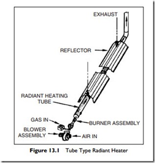
e Low intensity units are gas-fired, using the flue as the radiating element— basically a gas burner with a flue pipe (chimney) typically 20–30 feet long, with a 4-inch diameter, as shown in Figure 13.1. A low-intensity unit operates as a flue that runs horizontally through the space. It will usually, but not always, vent outside and have a reflector over the flue to reflect the radiant heat downward.
These low intensity units can run up to 1200°F, have a dull red glow, and take only three, or four, minutes to reach operating temperature. Since they are gas fired, adequate combustion-air must be provided, as required by local codes.
A single burner low intensity unit is shown in Figure 13.1. The blower assembly provides the required forced draft through the burner and long flue. The flue gas temperature drops as it gives up heat along the tube. As a result, the output drops along the length of the unit. Manufacturers can use different strategies to offset this drop in output; tube materials with a lower radiant output in the early sections, or larger tubes in the latter sections.
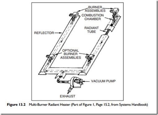
These strategies are not enough in larger installations, and so units with multiple burners are used. However, multiple-burner units introduce additional complexity into the system. For example, the same forced-draft method cannot be used, since, if one of the blowers failed, the others would blow fumes into the building through the inoperative blower. To avoid this possibility, multi-burner units have an exhaust fan, called a vacuum pump, to draw all the products of combustion from the flue. This is done to ensure that all flue gases are exhausted. This type of arrangement is shown in Figure 13.2. For further control of output, high-low, or modulating, burners can be used.
The burner controls are in the self-contained blower-burner assembly, with the whole unit controlled by a long-cycle (slow to respond) thermostat or a proprietary temperature control system. The location of this control is significant.
It is important to remember, from Chapter 3, that both ambient air temperature and the radiant effect of the heater(s) will affect the thermostat. Let us go back to the radiant floor for a simple example. If the thermostat is located on an inner wall (far away from the window), the floor and adjacent warm walls will pre- dominantly influence it. As a result the room tends to be cool for occupants in cold weather, since the cool external wall and windows do not adequately influence the thermostat. This effect is significantly reduced if the thermostat is placed on a side wall (nearer the window), well away from the inner wall so that the cool outside wall and window will have a more significant effect on the thermo- stat. This alternative could result in the room becoming uncomfortably warm.
The effect of location is even more pronounced with radiant heaters. As a result, it takes skill and experience to make an effective choice of thermostat location. This is one of those occasions when asking, and taking, the advice of an experienced manufacturer can be really worthwhile.
Since the multi-burner radiant-heater units run very hot, they must be out of the reach of occupants. They must also be mounted so that they cannot overheat objects immediately beneath them.
For instance, suppose a machine shop was fitted out with radiant heaters that were mounted 15 feet above the floor. This would provide a comfortable work environment for the staff. However, consider what would happen if the heaters were mounted directly above a floor space that was also used by delivery vehicles that drive into the shop to be loaded or unloaded. In that case, the top of the vehicles would be dangerously close to the heater and could end up with a burnt roof. This problem can often be avoided by designing the heater layout so the heaters are above the work areas only, at a safe distance from vehicle access routes.
Radiant heaters are particularly suitable where high spaces must be heated without obstructing the space, as in aircraft hangers, factories, warehouses, and gymnasiums. They are also valuable where the staff and floor is to be kept warm, but not the space, such as in loading docks, outdoor entrances, and swimming pools.
Radiant heaters are also suitable for racetrack stands and spectator seating around ice rinks. In the ice rink they have the ability to be directed at the seating with a fairly sharp cutoff to prevent heating the ice surface, and they do little to raise the air temperature that would also affect the ice.
Radiant Cooling
Radiant cooling was introduced in Section 3 of Chapter 8. Radiant cooling is always achieved by using a ‘large area’ panel system, since the transfer per square foot is quite limited. This is largely because the chilled-water temperature must be kept warm enough to avoid any condensation. The ceiling may be either a plastered ceiling with embedded pipes or a metal pan ceiling with the pipes attached to the panels.
Just like the radiant floor, the radiant cooling ceiling requires no equipment or floor space within the occupied area. With the plaster ceiling there is nothing in the room. This makes it an attractive choice in some hospital situations where cleaning needs to be minimized. Only ventilation air has to be moved around the building and supplied to each room. However, it is critical that the moisture level, relative humidity, in the building be kept low enough to prevent problems that may occur due to condensation on any part of the ceiling panels.
The performance of radiant ceilings is well understood by the various manufacturers of the many different designs and they, and the architect, should be involved early in the design stages. If a metal panel system is chosen, it must fit in with the dimensional requirements of the ceiling. Panels radiate upwards as well as downwards. An un-insulated panel will cool the space below as well as the floor or roof above it. If cooling is not desirable above the panel, the panel can have insulation placed on the top of it. Conversely, if the cooling is designed to radiate upwards, be sure that an acoustic pad is not specified above a panel, since the acoustic pad will also provide thermal insulation.
One negative of this system is the extended length of time it takes to return the space to comfort levels after the temperature has drifted up. Operators of radiant cooling panel systems need to be aware of the relatively slow response of these systems—even those with light metal panels. As a result, it is not a good idea to allow the temperature to drift up when the space is unoccupied, even though this strategy may appear to result in energy savings.

