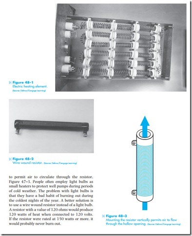
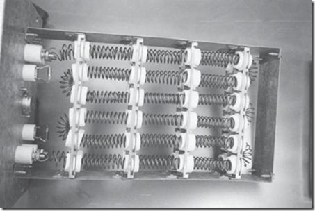
Resistors are among the most common components found in electrical circuits. It is sometimes necessary for a technician to be able to determine the value of a resistor in a circuit. Some resistors are intended to carry large amounts of current and produce heat, such as the resistors in electric heating systems, small space heaters, and the burners of an electric range, Figure 48–1. These resistors are generally made from a special type of wire called nichrome. Nichrome wire is about 65 times more resistive than copper and can be operated at very high temperatures.
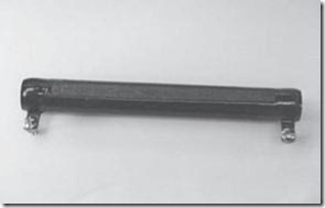
Wire wound resistors are made from nichrome wire also. These resistors are often made by winding nichrome wire on a hollow porcelain tube, Figure 48–2. Wire wound resistors of this type should be mounted vertically and not horizontally. The hollow portion of the resistor acts as a chimney
464
Electric heating element.
(Source: Delmar/Cengage Learning)
![]() Wire wound resistors generally have the ohmic value and power rating written on the resistor. If the ohmic value is not written on the resistor, an ohm- meter can be used to determine its value.
Wire wound resistors generally have the ohmic value and power rating written on the resistor. If the ohmic value is not written on the resistor, an ohm- meter can be used to determine its value.
Color Code
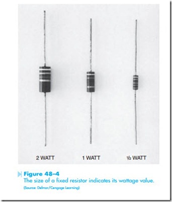
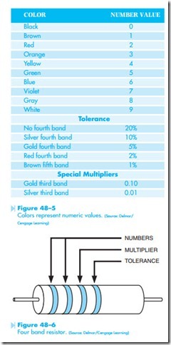
Small fixed resistors with ratings of 1/8 to 2 watts are generally marked with bands of color to indicate their ohmic value and tolerance. The size of the resistor indicates its wattage rating, Figure 48–4. Resistors can have from three to five bands of color. Most have four bands. The colors are used to indicate a numeric value. The chart in Figure 48–5 lists the colors and their corresponding number value. Resistors with a tolerance of ±20% will contain three bands of color. Resistors with a tolerance of ±10%, ±5%, and ±2% will contain four bands of color, and resistors with a tolerance of ±1% and some special purpose resistors will contain five bands of color. When determining the ohmic value and tolerance of a resistor with three or four bands of color, the first two bands represent
numbers, the third band is the multiplier, and the fourth band indicates the tolerance, Figure 48–6. If the resistor has a tolerance of ±10%, the fourth band will be silver. The fourth band will be gold for a resistor with a tolerance of ±5%, and red for a resistor with a tolerance of ±2%.
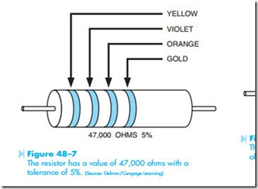
Assume a resistor has color bands of yellow, violet, orange, and gold, Figure 48–7. The first two
bands represent numbers. Yellow is 4 and violet is 7. The third band is the multiplier. Add the number of zeros indicated by the color. Orange is three, so add 3 zeros. The number becomes 47000. The resistor has a value of 47,000 ohms with a tolerance of ±5%.
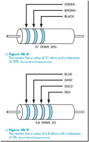
Now assume that a resistor has color bands of green, brown, black, Figure 48–8. Green is 5, brown is 1, and black is 0. The first two colors are numbers 51 and the third band color is black which is zero. This means there is no multiplier. The resistor has an ohmic value of 51 ohms. Since there is no third
Resistors that have a value less than 10 ohms use gold and silver in the third band as multipliers. When a resistor has a third band of gold it means to multiply the first two numbers by 0.1 or divide the first two numbers by 10. If the third band is silver, multiply the first two numbers by 0.01 or divide the first two numbers by 100. Assume a resistor has colors of blue, gray, gold, and red, Figure 48–9. Blue is 6, gray is 8 and gold means to divide by 10. The resistor has an ohmic value of 6.8 ohms. The red fourth band indicates a tolerance of ±2%.
Tolerance
The tolerance indicates the limits of ohmic value. Assume that a resistor is marked 1,000 ohms with a tolerance of ±10%. To determine if this resistor is within its tolerance rating, find 10% of the rated
Standard Resistance Values
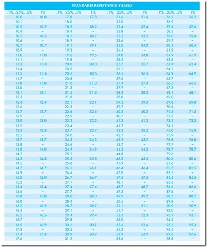
Fixed resistors are generally manufactured in standard values. The higher the tolerance value, the fewer resistance values available. Standard resistor values for different tolerances are listed in the chart shown in Figure 48–10. In the column under 10% only 12 values of resistance are listed. These standard values, however, can be multiplied by factors of 10. Notice that one of the standard values listed is 33 D. There are also standard values in
10% resistors of 0.33; 3.3; 330; 3300; 33,000; and 330,000, 3,300,00 D. Notice there is no listing for a value 32 or 34 ohms. They do not exist as a stan- dard value. The 2% and 5% column lists 24 stan- dard values and the 1% column lists 96 values. All of the values listed can be multiplied by factors of 10 to obtain other resistance values. Resistors with tol- erance ratings of 0.1%, 0.25%, and 0.5% generally have the resistance value printed on the resistor.
1% Value Resistors
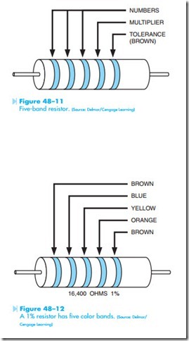
Notice in the chart shown in Figure 48–10 that the resistor values listed in the 1% column have three numeric numbers instead of two as is the case with 2%, 5%, and 10% values. Because resistors with a tolerance of 1% use three numbers instead of two, a five band resistor must be used to indicate their value, Figure 48–11. Assume a five band resistor has color bands of brown, blue, yellow, orange, and brown, Figure 48–12. The first three bands repre- sent numbers: brown = 1, blue = 6, and yellow = 4. The fourth band is orange, which means that you would multiply by 1,000 or move the decimal three places; 16.4 becomes 16,400 ohms. The fifth band is brown, which indicates a tolerance value of ±1%.
Other Fifth-Band Colors
Some resistors have five bands of color that are not 1% resistors. These are generally military markings. A resistor with a fifth band of yellow or orange is a reliability rating. The military often needs resistors that have been tested for reliability. It has long been known that if a resistor can operate within its tolerance for some number of hours without failure that the chances of failure become much smaller. The military often employs companies to test resistors for some period of time by operating them in a circuit and then checking the value to see if the resistor has remained within its tolerance rating.
Resistors with a fifth band of yellow are rated reliable enough for space flight equipment. An orange fifth band indicates the resistor is reliable enough for use in missile systems. A white fifth band indicates the leads are solderable.
