THE INPUT MODULE
The central processing unit of a programmable logic controller is extremely sensitive to voltage spikes and electrical noise. For this reason, the
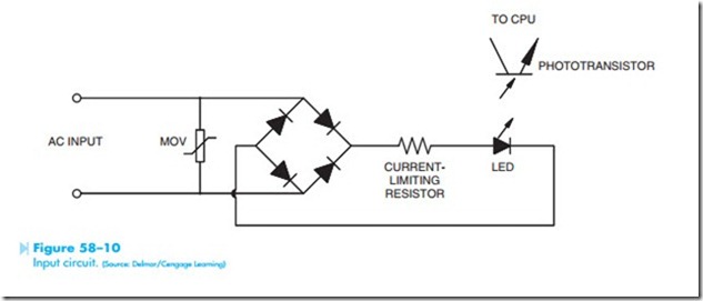
input I/O uses opto-isolation to electrically separate the incoming signal from the CPU. Figure 58–10 shows a typical circuit used for the input. A metal- oxide-varistor (MOV) is connected across the AC input to help eliminate any voltage spikes that may occur on the line. The MOV is a voltage-sensitive resistor. As long as the voltage across its terminals remains below a certain level, it exhibits a very high resistance. If the voltage should become too high, the resistance almost instantly changes to a very low value. A bridge rectifier changes the AC volt- age into DC. A resistor is used to limit current to a light-emitting diode. When power is applied to the circuit, the LED turns on. The light is detected by a phototransistor that signals the CPU that there is a voltage present at the input terminal.
When the module has more than one input, the bridge rectifiers are connected together on one side to form a common terminal. On the other side, the rectifiers are labeled 1, 2, 3, and 4. Figure 58–11 shows four bridge rectifiers connected together to form a common terminal. Figure 58–12 shows a limit switch connected to input 1, a temperature switch connected to input 2, a float switch connected to input 3, and a normally open pushbutton connected to input 4. Notice that the pilot devices complete a circuit to the bridge rectifiers. If any switch closes, 120 volts AC will be connected to a bridge rectifier, causing the corresponding light- emitting diode to turn on and signal the CPU that the input has voltage applied to it. When voltage is applied to an input, the CPU considers that input to be at a high level.
