Refrigeration Equipment
Heat naturally flows from warmer places to cooler places. Refrigeration equipment is used to transfer heat from a cooler place to a warmer place. In the domestic refrigerator, the refrigeration equipment absorbs heat from inside the refrigerator and discharges heat into the house. On a much larger scale, refrigeration machines are used to chill water that is then pumped around buildings to provide cooling in air-conditioning systems. The heat removed from the water is expelled into the atmosphere through a hot, air-cooled coil, or by evaporating water in a cooling tower.
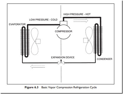
The domestic refrigerator and most other refrigeration systems use the same basic process of vapor compression and expansion. An alternative process, adsorption, is used but we are not covering it in this course. The vapor compression refrigeration system comprises four components: compressor, condenser, expansion valve, and evaporator. Figure 6.3 shows the arrangement.
Compressor—which compresses refrigerant vapor to a high pressure, making it hot in the process.
Condenser—in which air or water cooling reduces the temperature of the refrigerant sufficiently to cause it to condense into liquid refrigerant and give up its latent heat of evaporation. Latent heat of evaporation is the heat required to convert a liquid to a vapor at a particular temperature and pressure and is the heat released when a vapor condenses at a particular temperature and pressure.
Expansion valve—which allows a controlled amount of the liquid refrigerant to flow through into the low-pressure section of the circuit.
Evaporator—in which air or water heats the liquid refrigerant so that it evaporates (boils) back into a vapor as it absorbs its latent heat of evaporation.
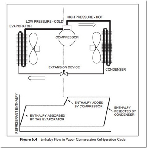
As the refrigerant flows round and round the circuit, it picks up enthalpy, heat, at the evaporator and more heat as it is compressed in the compressor. The sum of the evaporator and compressor enthalpy is rejected from the con- denser. The system effectiveness is higher, the greater the ratio of evaporator enthalpy to compressor enthalpy. One wants the most heat transferred for the least compressor work. The enthalpy flow into and out of the refrigerant is shown in the Figure 6.4.
In a very small, simple system, such as the domestic refrigerator, the expansion device is a length of very small-bore tube that restricts the refrigerant liquid flow from the high-pressure side to the low-pressure side. A thermostat in the refrigerator turns the compressor “on” when cooling is required, and “off” again when the inside of the refrigerator is cool enough.
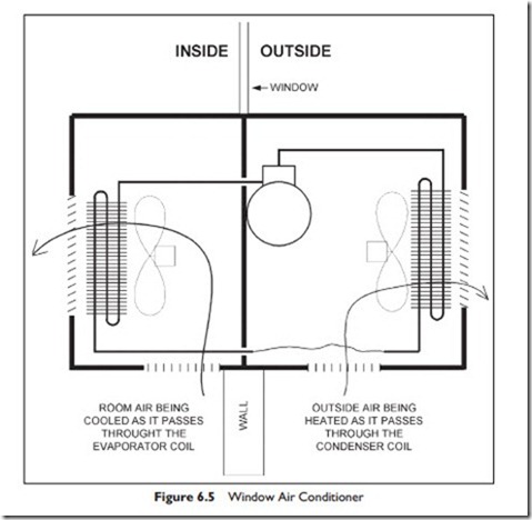
Moving up in size from the domestic refrigerator to the window air conditioner, Figure 6.5 shows the refrigeration circuit with a box around it. The evaporator fan draws room air over the evaporator coil to cool it. The con- denser is outside and the condenser fan draws outside air over the condenser coil to reject heat into the outside air.
The evaporator coil is designed to operate cool enough to produce some condensation on the coil. This condensate water is piped through to the outside and may just drip out of the unit or be evaporated in the condenser airflow.
The capacity of the unit is highest when the inside and outside temperatures are close to each other. As the outside temperature rises, so the capacity of the unit falls. It is therefore very important to know the anticipated maximum temperature at which the unit is to perform.
The refrigerator and the window air conditioner have air flowing across both the evaporator and condenser to achieve heat transfer. Many systems use water as an intermediate heat-transfer medium. The evaporator coil can be in a water-filled shell to produce chilled water. This chilled water can then be piped around the building, or even from building to building, to provide cool- ing as and where it is needed.
This central water-chilling plant can consist of one or more chillers that are sequenced to match their capacity with the load. In this way the noisy refrigeration equipment can be separated from occupied areas, and maintenance does not take place in occupied areas.
Water can also be used on the condenser side of the refrigeration system. Here the condenser heats the water, which is generally then pumped to one or more cooling towers. A cooling tower is a piece of equipment for cooling water by evaporation. The warmed condenser water enters at the top through a series of nozzles, which spread the water over an array of wooden or plastic surfaces.
Most cooling towers also have a fan to force air through the surfaces, causing some of the water to evaporate and cool the remaining water. The cooled water flows down into a sump, to be pumped back through the condenser.
Heat Pump
The previous discussion is focused on pumping heat from a cooled space and rejecting heat to outside. There are times when the reverse process is valuable. If the outside temperature is not too cold, one could install a window air conditioner back-to-front. Then, it would cool outside and warm inside. The total heat rejected to the inside would be the sum of the electrical energy put into the compressor, plus heat absorbed from the outside air. It would be pumping the heat into the space – hence we call it a heat pump. In milder climates, a heat pump can obtain useful heat from the ambient air.
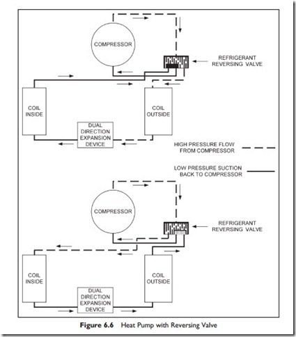
In practice, one does not take out the window air conditioner and install it the other-way-round for heating, since the reversal can be achieved with a special valve in the refrigeration circuit. Figure 6.6 shows the heat pump circuit. It has been drawn slightly differently from the previous two figures, but
the circuit is the same, evaporator, compressor, condenser, and expansion device. In the upper diagram the refrigerant is flowing, as in previous diagrams, and heat is being ‘pumped’ from the inside coil to be rejected by the outside coil. In the lower diagram the reversing valve has been switched to reverse the flow of refrigerant in the inside and outside coils. Heat in now absorbed from outside and rejected by the inside coil, heating the inside.
The performance of the air-to-air heat pump drops as the temperature difference increases, so they are not very effective with an outside air temperature below freezing.
Another source of heat, or sink for waste heat, is the ground. In many places, one can lay coils of pipe in the ground, in trenches or in vertical bore- holes, and circulate water. The water will be heated by the surrounding soil, if it is cold, and cooled by the surrounding soil if it is hot. In the example, shown in Figure 6.6, the heat pump has a ground water heated/cooled coil and a cooled/heated air coil for the building. Figure 6.6 shows the circuit, including the reversing valve operation.
Refrigeration is a very important part of the air-conditioning industry. The ASHRAE Course, Fundamentals of Refrigeration2 will teach you about the systems, components, system control and cooling loads.


