Unit Heater Piping Connections
The following general notes on piping propeller unit heaters are presented based on competent engineering installation practice:
1. Suspend unit heaters securely with provisions for easy removal.
2. Make certain that units hang level vertically and horizontally.
3. Provide for expansion in supply lines. Note swing joints in suggested piping arrangements.
4. Provide unions adjacent to unit heaters in both supply and return laterals. Also provide shutoff valves in all supply laterals.
5. Use 45°-angle runoffs from all supply and return mains.
6. Make certain that you have provided minimum clearances on all sides. Clearances will be specified in the heater manufacturer’s installation literature.
7. When required, dirt pockets should be formed with pipe of the same size as the return tapping of the unit heater.
8. Pipe in the branching line should be the same size as the tap- ping in the trap.
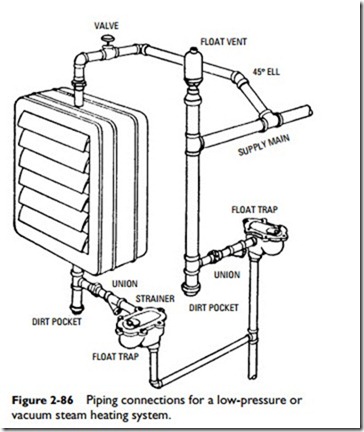
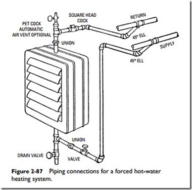
Figures 2-85 through 2-90 illustrate typical piping details for propeller-type horizontal unit heaters used in steam and hot-water heating systems.
The vapor steam system shown in Figure 2-85 uses an overhead steam main and a gravity dry return. Strainer and float-type steam traps are used between the unit heater and the return main. A float- type air vent is installed below the float trap.
As shown in Figure 2-86, the overhead steam main of a low- pressure or vacuum system can be vented and dripped independently. The steam supply to the unit heater is taken off the top of the main. The float vent is eliminated on systems using a vacuum pump.
Overhead supply and return mains are used (with bottom connections to the mains) in forced hot-water heating systems. The supply main is connected to the bottom of the unit heater. Either an automatic air vent or manual vent (pet cock) can be used at the high point on the return main (see Figure 2-87).
In the two-pipe steam system shown in Figure 2-88, the steam supply of the unit heater is taken from the top of the main. The return from the unit heater is vented before dropping to the wet return. The distance to the water line of the boiler must be sufficient to allow for the pressure drop in the piping.
Both an overhead supply main and an overhead return are used in the high-pressure steam system shown in Figure 2-89. The top of the bucket trap must be located below the return outlet of the coil for complete drainage of the condensation.
Unit heater piping connections for a Trane high-pressure steam system are illustrated in Figure 2-90. In this system, an overhead supply main is used with a lower return main. Where steam pressure fluctuates over a wide range, a swing-check valve should be placed in the return lateral between the strainer and the bucket trap to prevent reverse flow of the condensation or steam flashing when the pressure drops suddenly. The top of the bucket trap must be located below the return outlet of the coil for complete drainage of the condensation.


