Designing a Hydronic Radiant Floor Heating System
Design of a hydronic radiant floor heating system should be attempted only by those with the qualifications, training, and experience to do it right. It is very important that the design of a radiant panel heating system be correct at the outset. The fact that the coils or cables are permanently embedded in concrete, or located beneath
other materials, makes corrections or adjustments very difficult and expensive.
Many manufacturers of radiant panel heating system equipment have devised simplified and dependable methods for designing this type of heating system. In most cases, the manufacturer will provide any available materials to assist in calculating the requirements of a particular radiant floor heating system. Various design manuals, manufacturer-specific installation guides, and software tools are available for use in designing and sizing radiant floor heating systems.
A radiant floor heating system in which there is a constant (uninterrupted) circulation of water is the preferred design. The benefits of constant water circulation through the circuits are as follows:
• It maintains an even floor temperature.
• It prevents hot spots from forming when there is no call for heat.
• It prevents air from entering the system.
• It reduces the risk of the water freezing in systems where antifreeze cannot be used (that is, systems in which the water
 heater heats both the water for space heating and the water for cooking and bathing purposes).
The flow of water in some radiant heating systems is controlled by the circulator (pump). When the room thermostat calls for heat, the pump starts and rapidly circulates heated water through the radiant panels until the heat requirement is satisfied. The pump is then shut off by the thermostat. In some systems, a flow-control valve is forced open by the flow of water through the pipes as long as the pump is running, permitting free circulation of heated water through the system. When the pump stops, the control valve closes, preventing circulation by gravity, which might cause overheating. The principal disadvantage of a system with this off-on control is that it results in temperature lag and causes the panels to intermittently heat and cool.
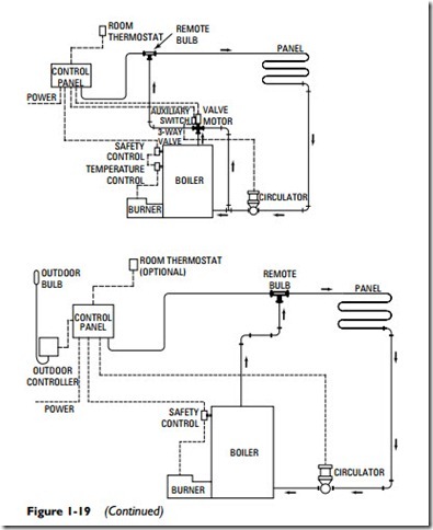
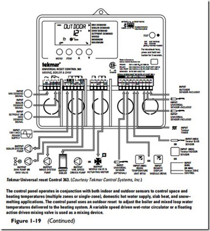
The continuous circulation of water through radiant heating panels is made possible by means of an outdoor-indoor control.
In this arrangement, hot water from the boiler is admitted to the sys- tem in modulated quantities when the temperature of the circulating water drops below the heat requirement of the panels. This modu- lated bleeding of water into the panel is accomplished through a bypass valve. When no additional heat is required, the valve is closed. When more heat is required, the valve is gradually opened by the combined action of the outdoor temperature bulb and a temperature bulb in the supply main. This system gives control by the method of varying the temperature of the water.
Air Venting Requirements
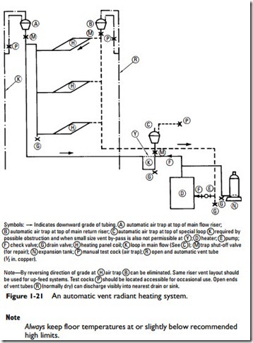
A common defect encountered in hot-water system design is improper venting. The flow of water should be automatically kept free of air binding throughout the system. Air in the pipes or pipe coils almost always results in a reduction of heat.
A practical method of venting is shown in Figure 1-21. The key to this method is the use of automatic air vents. Each air vent should be located in an area readily accessible for repair. The air trap test cock should be placed where it can be easily operated. Both the air trap and the air trap test cock must be located where they are not subject to freeze-up, as both are noncirculating except during venting operation (automatic or manual).
Sizing Calculations
The successful operation of any hot-water heating system requires the incorporation of design provisions that ensure an even and balanced flow of water through the pipes or coils of the installation.
The procedure for designing a hydronic radiant floor heating system may be outlined as follows:
1. Determine the total rate of heat loss per room in the structure.
2. Determine the available area for panels (loops) in each room.
3. Determine the output required by each panel to replace the heat loss.
4. Determine the required surface temperature for each panel.
5. Determine the required heat input to the panel (should equal heat output).
6. Determine the most efficient and economical means of sup- plying heat to the panel.
7. Install adequate insulation on the reverse side and edges of the panel to prevent undesirable heat loss.
8. Install the panels opposite room areas where the greater heat loss occurs.
Radiant Floor Construction Details
Radiant floor construction can be divided into two broad categories based on the installation method used: (1) wet installation and (2) dry installation. The wet installation method involves completely embedding the tubing in a concrete slab or covering it with a thin layer of concrete (commonly a gypsum-based lightweight pour).
The dry installation method is so-called because the tubing is installed without embedding it in concrete.
The examples of radiant floor construction described in this sec- tion represent the most commonly used forms. They are offered here only as examples, not as planning guides for contractors. The actual construction plans will depend on the design of the hydronic radiant floor heating system, the impact of local building codes and regulations, and other variables.
Slab-on-grade construction
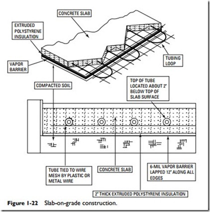
In slab-on-grade construction, the tubing is attached to a wire mesh or special holding fixtures to keep it in place until the concrete is poured around it. The tubing loops are embedded in the middle of the concrete slab and are located approximately 2 inches below the slab surface (see Figure 1-22). A brief summary of the steps involved in slab-on-grade construction is as follows:
1. Compact the soil base to prevent uneven settling of the slab.
2. Cover the compacted soil with a lapped 6-mil vapor barrier.
3. Cover the vapor barrier with 2-inch-thick extruded polystyrene insulation.
4. Install rigid polystyrene insulation vertically on the inside surface of the exterior foundation walls to prevent edgewise (horizontal) heat loss.
5. Lay concrete reinforcing mesh over the insulation.
6. Position the tubing on top of the reinforcement mesh according to the tubing layout plan.
7. Tie the tubing to the reinforcement mesh with tie straps or wire.
8. Cover the tubing with a minimum of 9 inches of concrete.
Thin-Slab Construction
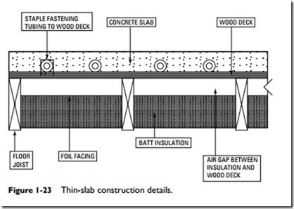
In this type of wet installation, a layer of lightweight concrete or lightweight gypsum is poured over the tubing to form a thin slab (see Figure 1-23). Thin-slab construction is used over a wood sub- floor supported by wood framing.
A summary of the steps involved in forming a thin-slab floor system using poured concrete to form the slab may be outlined as follows:
1. Apply a lapped 6-mil polyethylene vapor barrier to the wood subfloor.
2. Position the tubing on the subfloor according to the tubing layout plan.
Fasten the tubing to the wood subfloor with plastic clips or metal staples.
4. Pour concrete over the tubing and subfloor.
5. Install batt insulation in the joist cavities beneath the subfloor.
If lightweight gypsum cement instead of concrete is used to form the slab, pour the gypsum in two stages. The first pour should be no higher than the tops of the tubes. When this first layer dries, it will shrink slightly and pull back from the tub- ing. Apply a second layer of gypsum to completely cover the first layer and the tops of the tubing.
Sandwich Floor Construction
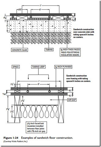
Sandwich floor construction is available in a number of different configurations (see Figure 1-24). This construction method involves
locating the tubing between the subfloor and additional flooring layers. In some cases, aluminum plates are added for heat dispersion. The two layers of a sandwich floor have wood sleepers installed between them for adding the tubing and subsequent flooring layers. These systems all contain less thermal mass than slab systems, and some allow for more rapid temperature responsiveness.
Staple-Up Method
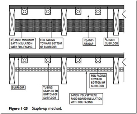
In the staple-up method, the tubing is located below the subfloor. This method of installing tubing is very common in both new construction and remodeling work. Its use is recommended when retrofitting because it avoids the problem and expense of having to remove the existing floor covering.
Note
The staple-up construction method will require drilling holes for the tubing in some of the supporting joists.
The staple-up construction method illustrated in Figure 1-25 is used without heat transfer plates. The tubing is fastened to the bot- tom of the subfloor in the joist cavities. Install either 31⁄2-inch batts or 2-inch polystyrene rigid insulation in the joist cavities below the tubing with a 11⁄2- to 4-inch air gap between the subfloor and the insulation.
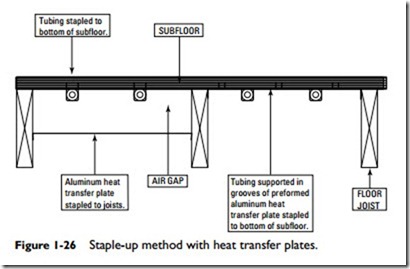
The heating efficiency of the staple-up construction method can be greatly improved by adding preformed, grooved aluminum heat transfer plates beneath the subfloor (see Figure 1-26). The plates are stapled to the bottom of the subfloor in the joist cavities, and the tubing is inserted in the preformed plate grooves. Insulation is installed beneath the tubing with a 2- to 4-inch air space between the top of the insulation and the bottom of the subfloor. The heat from the tubing spreads horizontally across the plate surface and then flows upward into the room or space above the floor. Without these plates, a percentage of the heat from the tubing is lost because it flows down into the spaces below the room being heated. To compensate for the heat loss, the heating system must operate at higher temperatures. This results in higher heating costs.
A variation of the staple-up construction method is to hang the tubing several inches below the subfloor in the joist cavities. Aluminum heat-transfer plates are fastened to the bottoms of the floor joists leaving an air gap between the plates and the bottom of the subfloor.
Tubing Installed Above the Subfloor
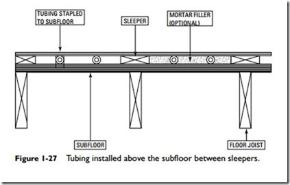
Figure 1-27 illustrates a common dry installation method of installing the tubing above the subfloor. It consists of wood sleepers nailed to the top surface of the wood subfloor with the tubing located in the spaces between the sleepers. Plywood is nailed to the tops of the sleepers to support the floor covering material.
Note
A loose, noninsulating masonry filler poured around the tubing will increase the thermal mass of the floor. Do not use loose fill insulation, such as perlite or vermiculite. These are insulating materials that will interfere with the heat radiation from the tubing. Masonry filler is not an insulating material.
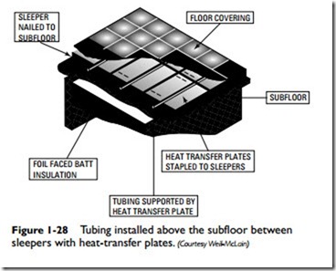
An alternative method is to install heat-transfer plates between the sleepers and use the plates to support (cradle) the tubing. In both cases, a suitable insulation must be installed between the floor joists (see Figure 1-28).
Still another method is to install factory-made, grooved wood panels beneath the finished floor. The dimensions of the panels may vary, depending on the manufacturer. The tubing is inserted in the panel grooves and set flush with the panel surface.
Floor Coverings
Floor covering materials reduce the amount of heat radiation rising into the room or space above the floor. The insulating properties of floor coverings must be considered when designing a hydronic or electric radiant floor heating system. Plush carpets and polyurethane carpet pads should not be installed over a radiant floor heating system. The same holds true for thick wood floors or multiple layers of plywood subfloors. Both have a high thermal resistance.
Carpets are commonly installed over a carpet pad. The combined carpet and cushion R-value (that is, its insulating value) should not exceed a maximum of R-4.0. Use either a foam rubber or waffle rubber pad. To reduce the resistance even further, con- sider eliminating the carpet pad.
Sheet final and tile floor coverings radiate the heat much faster than carpet, thereby reducing the lag time between when the hot water flows through the circuit and the heat is actually delivered to the room or space above.
