Coils and Coil Patterns
Hydronic radiant floor heating panels are available as prefabricated units, or they can be constructed at the site. The principal coil pat- terns used in radiant floor heating systems are the following:
1. Coil pattern for uniform heat distribution.
2. Coil pattern for perimeter heat distribution along two walls.
3. Coil pattern for perimeter heat distribution along one wall.
Counter flow Spiral Tube Layout Pattern
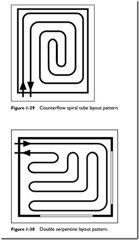
The tube layout illustrated in Figure 1-29 provides the most even and uniform heat distribution for a room in a radiant floor heating system. It accomplishes this by running the supply and return lines parallel to one another. As a result, an average temperature is created between the tubes.
Double Serpentine Layout Pattern
In some rooms, there will be a significant amount of heat loss through two adjacent exterior walls. As shown in Figure 1-30, the supply tubing runs along the perimeter of the walls where the hot water can provide maximum heat transfer. It then turns inward in a series of serpentine-like loops to the center of the room (the area of lowest heat loss) before returning to the manifold.
Single Serpentine Layout Pattern
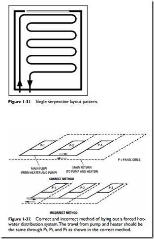
If a major heat loss occurs along a single exterior wall, the supply tubing runs along the perimeter of that wall before returning in a series of serpentine loops to the return manifold (see Figure 1-31).
In a well-designed hydronic radiant floor heating system, the linear travel from the heating unit and pump should be the same for each of the panels (see Figure 1-32). This will result in the flow through each panel being in natural balance.

