Design considerations for rotor exit
Several decisions need to be made regarding the design of the rotor exit. The flow angle β3, the meridional velocity to blade tip speed ratio cm3/U2, the shroud tip to rotor tip radius ratio r3s/r2, and the exit hub-to-shroud radius ratio ν 5 r3h/r3s, all have to be considered. It is assumed that the absolute flow at rotor exit is entirely axial so that the relative velocity can be written as
If values of cm3/U2 and r3/r2 can be chosen, then the exit flow angle variation can be found for all radii. From the rotor exit velocity diagram in Figure 8.3,
The meridional velocity cm3 should be kept small in order to minimize the exhaust energy loss, unless an exhaust diffuser is fitted to the turbine.
Rodgers and Geiser (1987) correlated attainable efficiency levels of IFR turbines against the blade tip speed-spouting velocity ratio, U2/c0, and the axial exit flow coefficient, cm3/U2, and their result is shown in Figure 8.8. From this figure, it can be seen that peak efficiency values are obtained with velocity ratios close to 0.7 and with values of exit flow coefficient between 0.2 and 0.3.
Rohlik (1968) suggested that the ratio of mean rotor exit radius to rotor inlet radius, r3/r2, should not exceed 0.7 to avoid excessive curvature of the shroud. Also, the exit hub-to-shroud radius ratio, r3h/r3s, should not be ,0.4 because of the likelihood of flow blockage caused by closely spaced vanes. Based upon the metal thickness alone, it is easily shown that
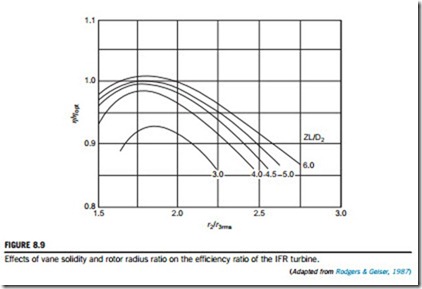
where t3h is the vane thickness at the hub. It is also necessary to allow more than this thickness because of the boundary layers on each vane. Some of the rather limited test data available on the design of the rotor exit comes from Rodgers and Geiser (1987) and concerns the effect of rotor radius ratio and blade solidity on turbine efficiency (Figure 8.9). It is the relative efficiency variation, η/ηopt, that is depicted as a function of the rotor inlet radius-exit root mean square radius ratio, r2/r3rms, for various values of a blade solidity parameter, ZL/D2 (where L is the length of the blade along the mean meridian). This radius ratio is related to the rotor exit hub-to-shroud ratio, ν, by
Rohlik (1968) suggested that the ratio of the relative velocity at the mean exit radius to the inlet relative velocity, w3/w2, should be sufficiently high to assure a low total pressure loss. He gave w3/w2 a value of 2.0. The relative velocity at the shroud tip will be greater than that at the mean radius depending upon the radius ratio at rotor exit.
EXAMPLE 8.4
Given the following data for an IFR turbine,
EXAMPLE 8.5
Using the data and results given in Examples 8.3 and 8.4 together with the additional information that the static pressure at rotor exit is 100 kPa and the nozzle enthalpy loss coefficient, ζN 5 0.06, determine
a. the diameter of the rotor and its speed of rotation; and
b. the vane width to diameter ratio, b2/D2 at rotor inlet.
Solution
a. The rate of mass flow is given by
EXAMPLE 8.6
For the IFR turbine described in Example 8.3 and using the data and results in Examples 8.4 and 8.5, deduce a value for the rotor enthalpy loss coefficient, ζR, at the optimum efficiency flow condition.
Solution
From Eq. (8.10), solving for ζR,


