Criterion for minimum number of blades
The following simple analysis of the relative flow in a radially bladed rotor is of considerable interest as it illustrates an important fundamental point concerning blade spacing. From elementary mechanics, the radial and transverse components of acceleration, fr and ft, respectively, of a particle moving in a radial plane (Figure 8.6a) are
which is merely the inviscid form of Eq. (8.2a).
The torque transmitted to the rotor by the fluid manifests itself as a pressure difference across each radial vane. Consequently, there must be a pressure gradient in the tangential direction in the space between the vanes. Again, consider the element of fluid and apply Newton’s second law of motion in the tangential direction:
which establishes the magnitude of the tangential pressure gradient. Differentiating Eq. (8.38) with respect to θ,
This result establishes the important fact that the radial velocity is not uniform across the pas- sage as is frequently assumed. As a consequence the radial velocity on one side of a passage is lower than on the other side. Jamieson (1955, chap. 9), who originated this method, conceived the idea of determining the minimum number of blades based upon these velocity considerations.
Let the mean radial velocity be w and the angular space between two adjacent blades be Δθ 5 2π/Z, where Z is the number of blades. The maximum and minimum radial velocities are, therefore,
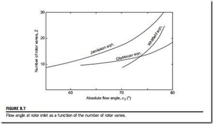
Jamieson’s result, Eq. (8.43b), is plotted in Figure 8.7 and shows that a large number of rotor vanes are required, especially for high absolute flow angles at rotor inlet. In practice, a large number of vanes are not used for several reasons, e.g., excessive flow blockage at rotor exit, a disproportionally large “wetted” surface area causing high friction losses, and the weight and inertia of the rotor become relatively high.
Some experimental tests reported by Hiett and Johnston (1964) are of interest in connection with the analysis just presented. With a nozzle outlet angle α2 5 77o and a 12 vane rotor, a total-to static efficiency ηts 5 0.84 was measured at the optimum velocity ratio U2/c0. For that magnitude of flow angle, Eq. (8.43b) suggests 27 vanes would be required to avoid reverse flow at the rotor tip. However, a second test with the number of vanes increased to 24 produced a gain in efficiency of only 1%. Hiett and Johnston suggested that the criterion for the optimum number of vanes might not simply be the avoidance of local flow reversal but require a compromise between total pressure losses from this cause and friction losses based upon rotor and blade surface areas.
Glassman (1976) preferred to use an empirical relationship between Z and α2, namely,
as he also considered Jamieson’s result, Eq. (8.43b), gave too many vanes in the rotor. Glassman’s result, which gives far fewer vanes than Jamieson’s is plotted in Figure 8.7. Whitfield’s result, given in Eq. (8.31c), is not too dissimilar from the result given by Glassman’s equation, at least for low vane numbers.


